| START HERE |
|
| Register | FAQ | PM | Events | Groups | Blogs | Calendar | Mark Forums Read |
|
|
|
Unregistered
|
||||||


| Gas Powered Thoughts Advice for Gas Helicopter Success from Carey Shurley |
|
|
 |
|
|
LinkBack | Thread Tools | Display Modes |
 08-20-2013, 08:46 PM
|
#1 (permalink) |
|
Registered Users
Join Date: Apr 2004
|
 Overview  HWC has completed the design of their latest gas conversion for the Trex 700. This is the first helicopter kit offered by HWC or Century Helicopter for the RC format of the Zenoah engine. 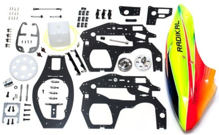 Photo Courtesy Century Helicopter The kit is very complete. You need the basic components from a Trex 700 plus your electronics and a Zenoah RC format engine to complete the conversion. The following are the parts needed from a "donor" Trex 700. This conversion is for the traditional Trex 700 model that uses a bellcrank control system
 Required parts from Trex 700 donor model Additional Required Parts No additional parts are required for the conversion. Everything needed to make the conversion is included You'll of course need an engine, muffler, blades and electronics. Last edited by carey shurley; 05-27-2020 at 01:09 PM.. |

|


|
| Sponsored Links | |||
|
Advertisement |
|
||
|
08-21-2013, 10:29 PM
|
#2 (permalink) |
|
Registered Users
Thread Starter

Join Date: Apr 2004
|
Pre-Assembly - Chassis
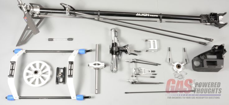
Like most models if some pre-assembly is done it really simplifies completing the converson. This one is no different so I want to go through some pre-assembly first with chassis parts and then with the engine Here you can see all the parts, both from the donor model and from the kit that are needed for this segment of the assembly. Its not a requirement that you follow this order of assembly 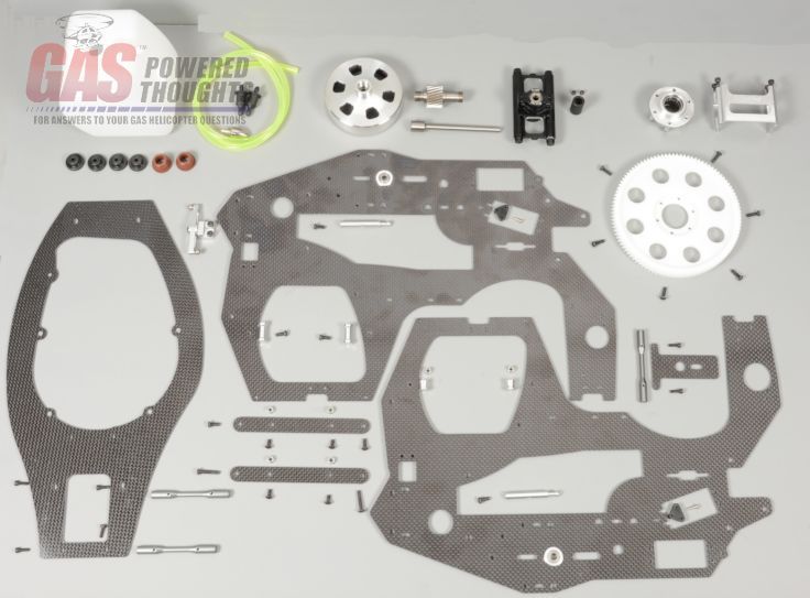 Chassis components for pre-assembly The kit comes with a 103 tooth helical main gear. The newer Trex models have helical gears but the older ones do not. Doesn't matter you won't need the original main gear. You do need the main drive hub and bolts from the donor model though. The new main gear is recessed just like the original and assembles the same way 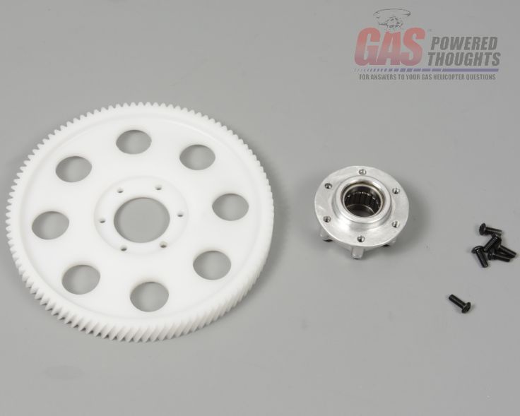 Parts to assemble main gear Combine these as shown and use thread lock on the bolts. Set aside until later 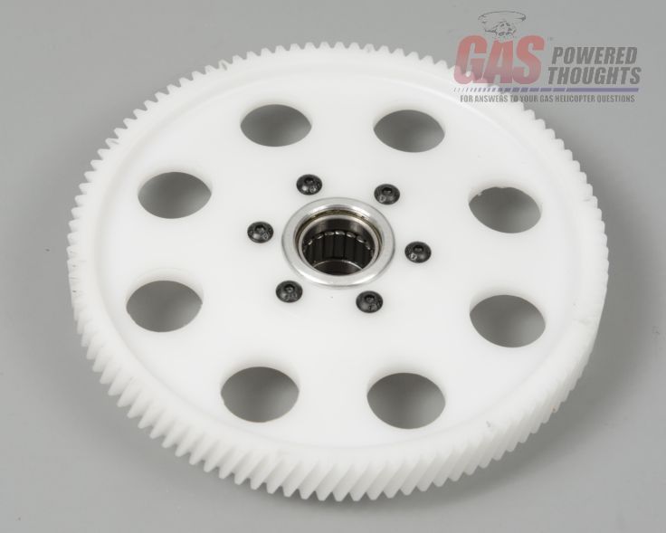 Main gear assembled This kit comes with a new canopy and has its own method of mounting. The frames are made so that you CAN use the original Trex canopy if you want in which case you won't need this part, but if you want to use the included Century canopy then located these parts and assemble the front canopy mount 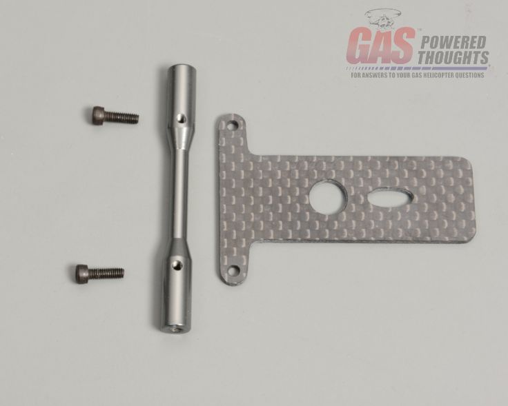 Front canopy mount parts use thread lock and set this aside for later 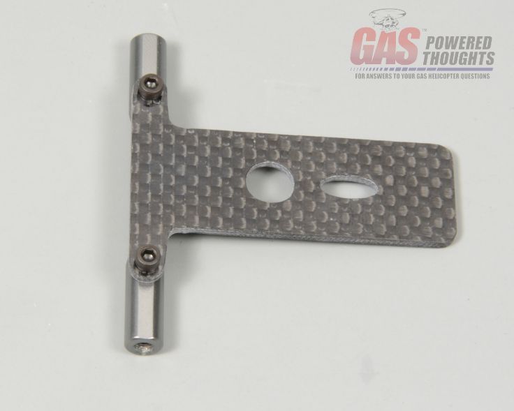 Front canopy mount assembled Like all RC format based helicopters, there is a bottom engine mount plate that the engine will be bolted to. Before putting the engine in the plate there is some work to do. Locate the plate and two cross member plates as shown 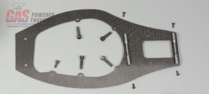 Parts to assemble bottom plate Note the orientation of the cutouts on the plate bolt the two cross members to the "top" of the plate as shown. The cross members have "flats" on them, make sure they are against the plate. You'll also note these mount holes in the plate are slotted, this is to account for optional pinion gears so don't thread lock or fully tighten these bolts at this point 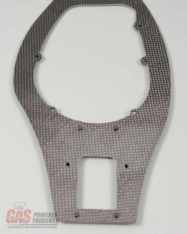 Bottom plate assembled On the main frame sides. I started with the left side and these are the parts used. The cutouts in the frame sides are identical BUT the bearing holders for the elevator are NOT. So pay attention to this the bearing holders will be on the outside of each frame which will identify them as left and right. 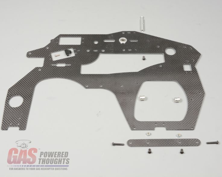 Parts to assemble left frame The fuel tank is isolated and is sandwiched between two mount plates on the frame. Start by installing the short bolts and lock nuts onto them as shown. They are not directional just make sure both bolts/nuts are on the same side of each retainer 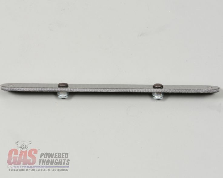 Fuel tank retainer Because the muffler is on the left side of the model, the tank is offset to the right side of the model. To that end the spacers that hold the tank mount plate are shorter on the left side. They also mount differently on each side. On the left side the tank mount is held in place by two longer bolts that go through the frame side Left side fuel tank retainer spacers here you can see the left fuel tank mount positioned on the frame with the shorter spacers in place with the mount bolts through the frame 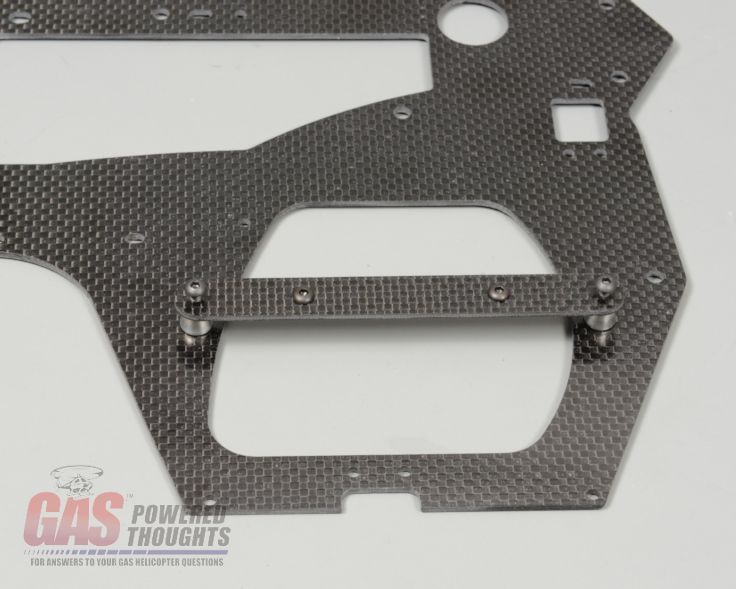 Left side fuel tank retainer in position These bolts are retained with locknuts inside the frame as shown 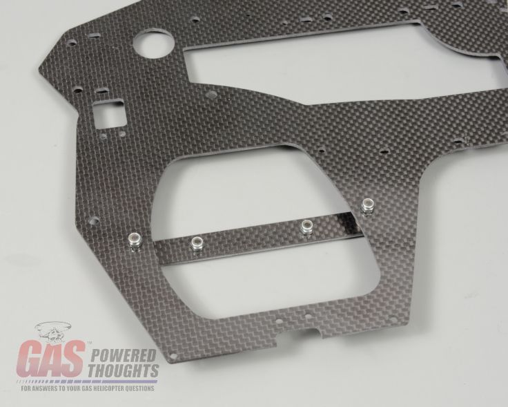 Left fuel tank retainer installed Install the provided left canopy mount as shown if you are using the included Century canopy 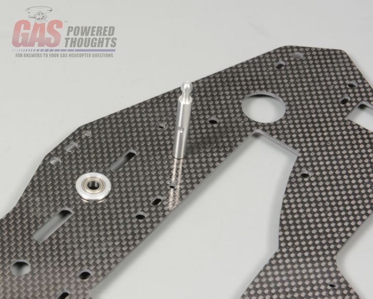 Install left rear canopy mount - Century Canopy If you intend to use the original Align canopy then instead mount one of the original rear canopy mounts in the alternate position shown here  Install left rear canopy mount - Trex Canopy As with the original model, the aileron/collective servos mount into the frames using some plastic servo nuts that attach to the frame. HWC includes these in the conversion so you can mount one of them as shown using the supplied screw. Don't fully tighten this yet until later when the servo is installed so that the spacing will be correct for your servo. 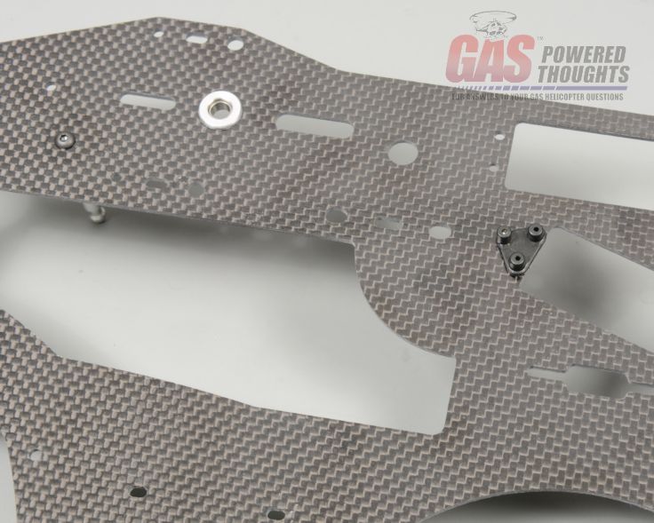 Left frame servo nut installed As with the original model, the elevator servo is installed into a carrier on the left frame so that it is properly positioned. Go ahead and install that now using thread lock if you have the aluminum parts or CA if you have the plastic parts 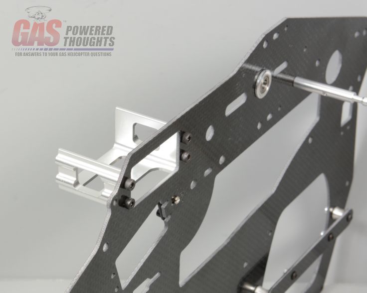 Elevator servo mount installed That wraps up the left frame pre-assembly now we'll do the right side which is almost identical. Again note the position of the bearing holder as this will indicate which frame is for the right. These are the parts for the pre-assembly and you can see that I've already installed the right rear canopy mount (for the Century canopy) and the fuel tank mount stand-offs. Note that the fuel tank standoffs on the right side are longer and are retained to the frame using bolts from the inside. Thread lock all of these parts into place 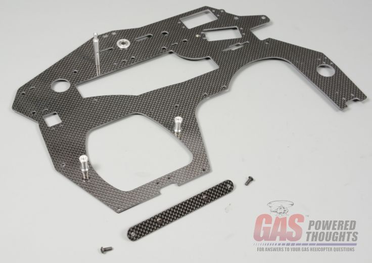 Parts to assemble right frame If you intend to use the original Align canopy then instead mount one of the original rear canopy mounts in the alternate position shown here 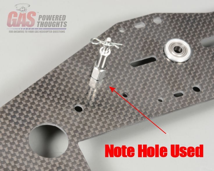 Install Right rear canopy mount - Trex Canopy And here's the right frame completed. Note that the original rudder bellcrank has been bolted into place as well as the right side fuel tank retainer which mounts using two short bolts. All of these can be thread locked into place as well 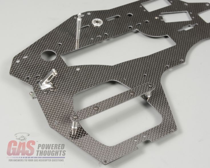 Right frame completed Now to to the fuel tank. This conversion is a bit unusual in that it has a custom molded fuel tank that FINALLY includes the right number of fittings to plumb a gas helicopter!!! Here are the parts you'll need to build the fuel tank pickup. Some notes here. The kit includes the yellow tubing you see. Its too stiff to put inside the fuel tank so don't use it. Instead use the black Viton tubing that comes with the RC motors. Its much more flexible. Next the kit includes a metal clunk. Replace it with a felt clunk. The RC motors come with a felt clunk its too big to get through any of the holes on this tank. Get a Stens #610-014 as shown, its smaller and will fit through the holes 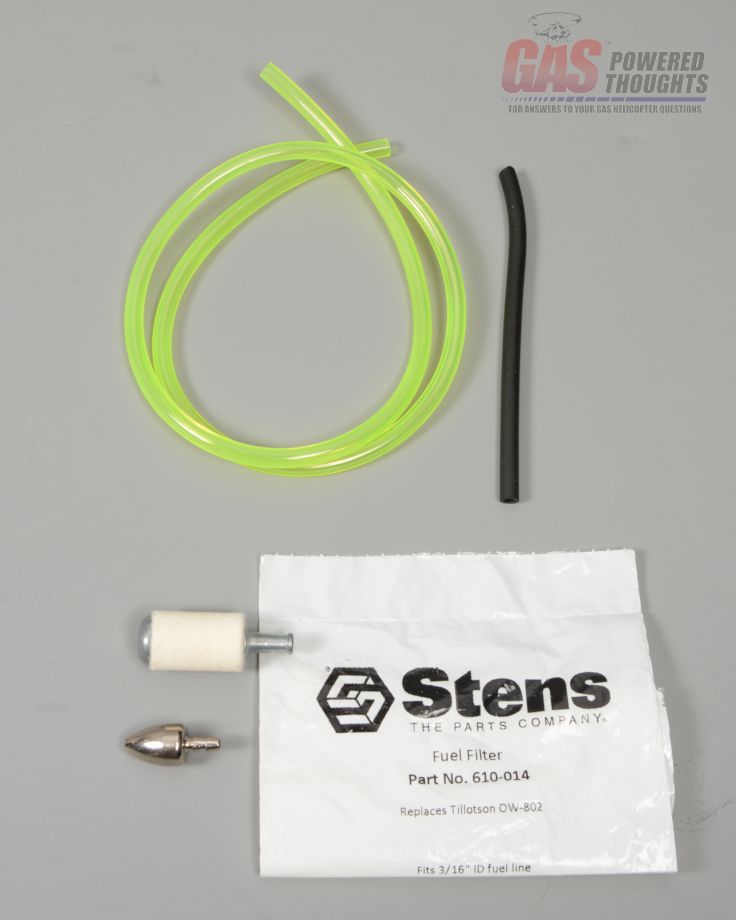 Fuel tank pickup parts Build the fuel tank pickup as shown. Cut the pickup tubing to a length of 4". BTW if you decide to instead use neoprene for this tubing, expect it to split over the fittings so you'll want to check it occasionally, 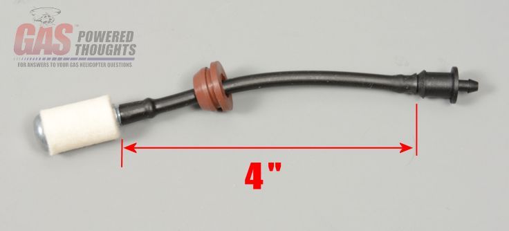 Fuel tank pickup assembledf The return fitting for the tank goes into the top as shown. Work one of the brown grommets into the tank and then push the fitting into it 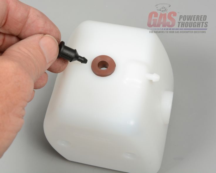 Fuel tank return fitting Heres the fuel tank return fitting installed 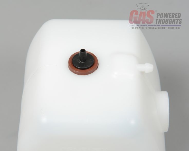 Fuel tank return installed The kit includes four rubber tank isolators, push them into the fuel tank as show. This will pop into place and shouldnt' require any adhesive 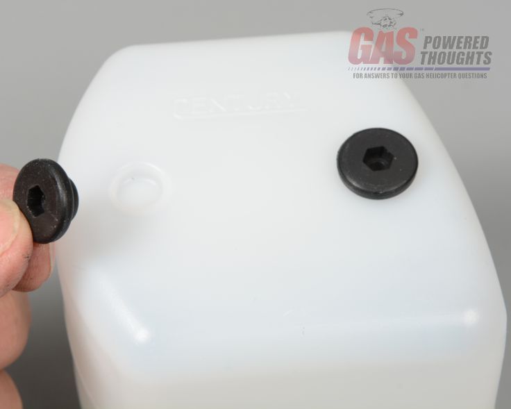 Install fuel tank isolators Install the fuel tank pickup through the hole in the front of the tank. You'll need to work the felt clunk a little bit to get it through but it will fit. Once its in then seat the brown grommet in the tank and finally push in the fitting 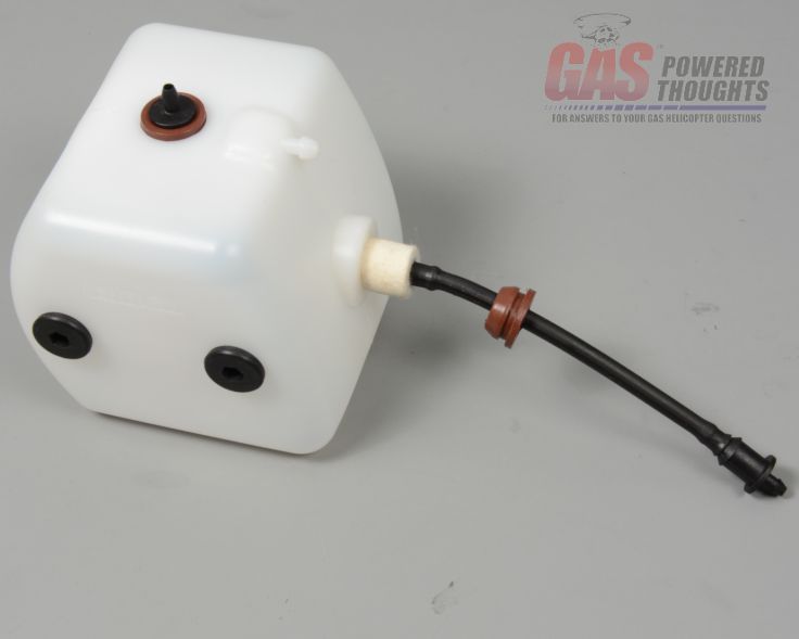 Insert fuel tank pickup when you're done, the fuel tank assembly should look like this 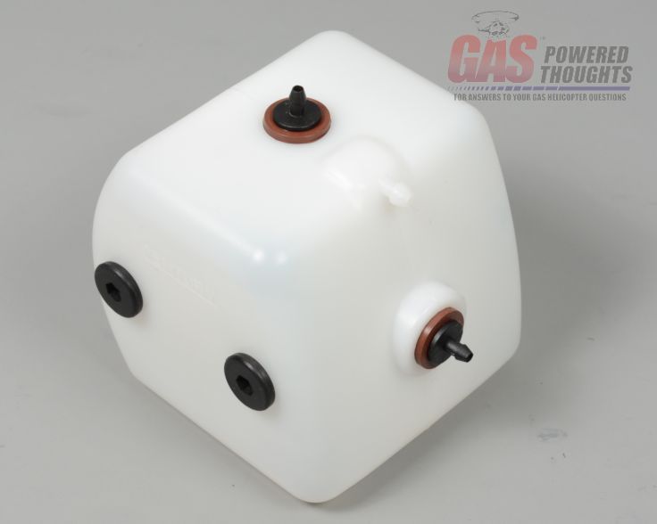 Completed fuel tank To assemble the clutch bell you'll need the clutch bearing block/bearings from the donor model, these may be plastic or you may have upgraded to the metal part shown. The procedure will be the same either way. The kit includes a 17T helical pinion gear and this large clutch bell. This is the Century HD clutch and it works very well on gas helicopters. They get credit from me for providing both a clutch that really locks up well AND still has a method for spin starting the engine. Most conversions choose one or the other but not both. 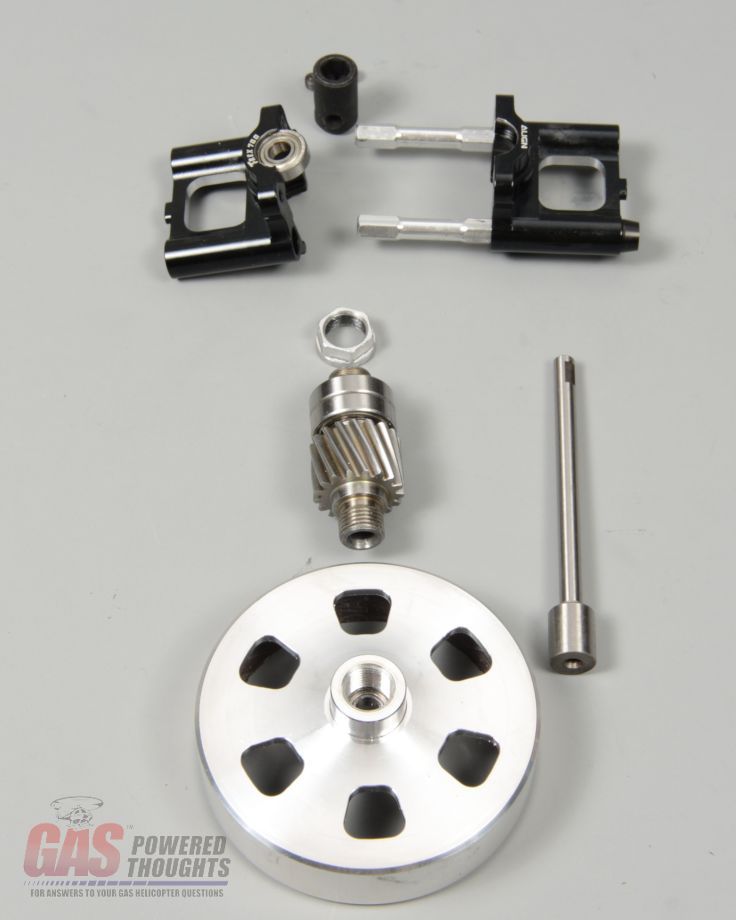 Clutch bell parts The pinion goes together in the usual way, the radial bearings slip over the pinion and the retaining nut is snugged into place with thread lock 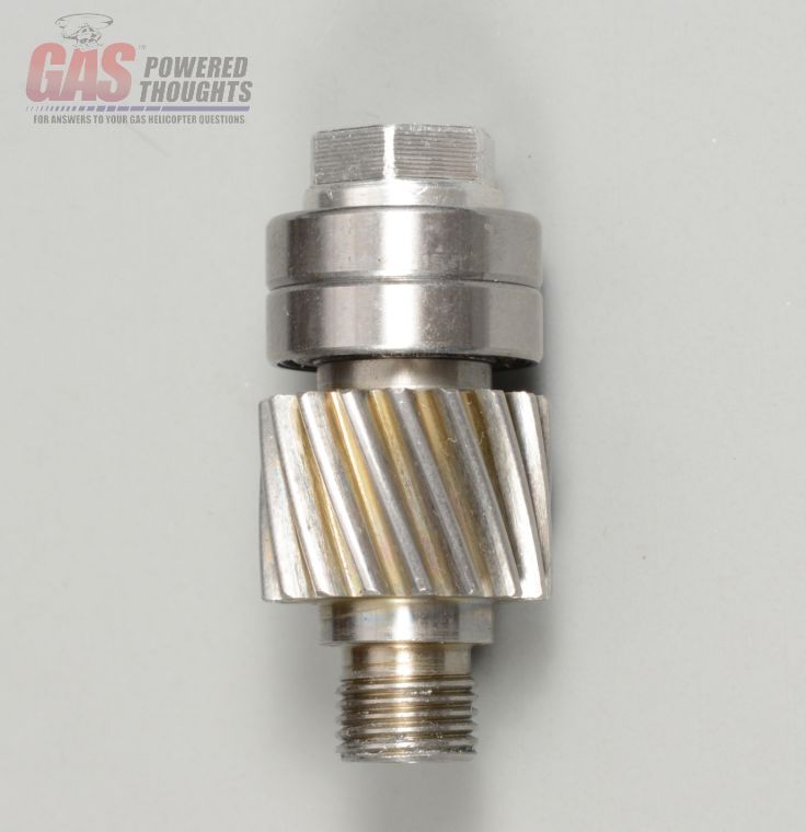 Install Pinion bearings The clutch bell threads over the pinion as shown. You can use some blue thread lock on this but its reverse threaded so its not going to come off in use 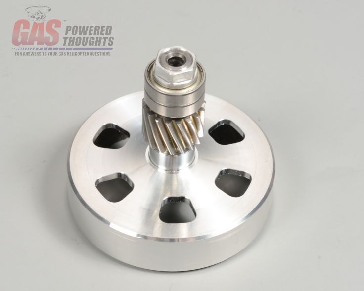 Clutch bell installed The pinion installs into the bearing block in the usual way it fits into the clutch bearing block 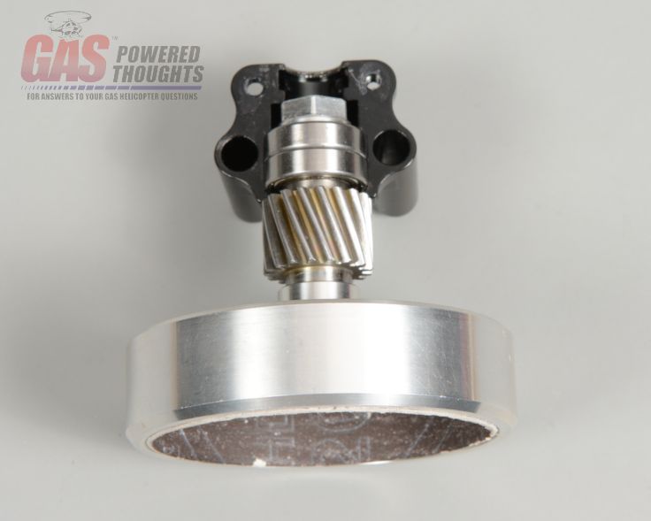 Assemble clutch bearing block Use the included start shaft and push it through the clutch bearing inside the bell as shown 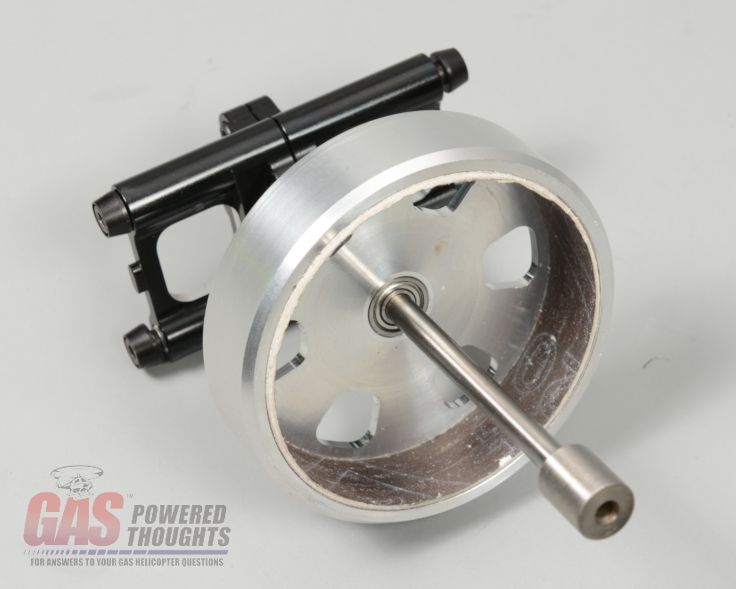 Start shaft inserted Finally install the included starter coupler using the M3 set screws. Make sure you position one of the set scews on the flat on the shaft. Use thread lock and fully tighten This concludes the clutch assembly, set it aside for later 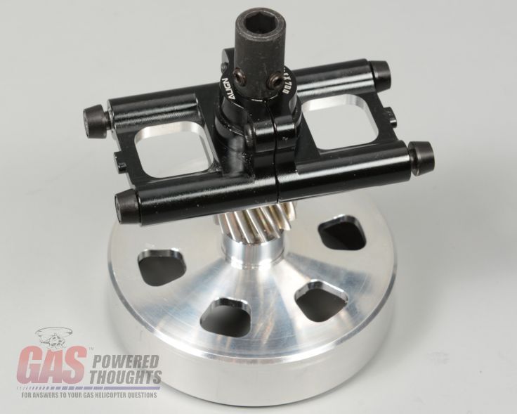 Clutch bell assembly completed Next Step Engine Preparation Last edited by carey shurley; 05-27-2020 at 01:11 PM.. |
|
|
|
|
08-23-2013, 06:48 AM
|
#3 (permalink) |
|
Registered Users
Thread Starter
Join Date: Apr 2004
|
Engine Preparation
In this step the engine will be prepared for installation. Whether you use a traditional ignition RC format motor or an electronic ignition engine such as the HWC these steps will be the same 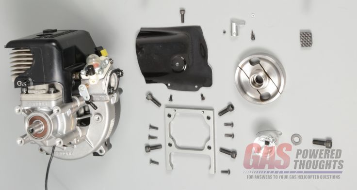 Parts to prepare engine Because the engine mounts into the chassis facing forward, the hot air from the cooling system is blowing upward. Traditionally this winds up letting hot air blow into the canopy which can overheat the electronics. HWC created a deflector that extends outside of the canopy to address this. In order to mount it the first step is to remove this screw 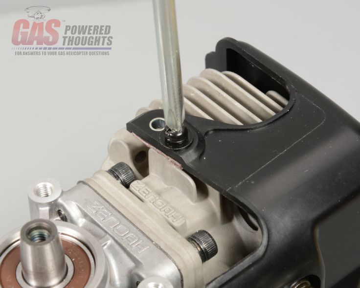 Remove original shroud mount bolt The engine mount bolts onto the front of the crankcase as shown using the M4 bolts that are included. Use thread lock and fully tighten these. The mount doesn't have an up/down side orientation but the open end of the mount must be oriented as shown 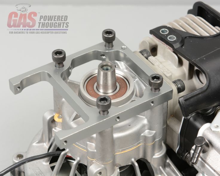 Engine Mount install This is the air deflector discussed earlier, its going to mount as shown  Position for air deflector The deflector mounts using the included bolts. Use thread lock on the engine mount bolts and RTV on the bolt that goes into the cylinder. This deflector is made from fiberglass and may have warped slightly over time. If it does not fit snugly onto the top of the cooling shroud, use a heat gun and warm it slightly so that you can fit it to the right shape 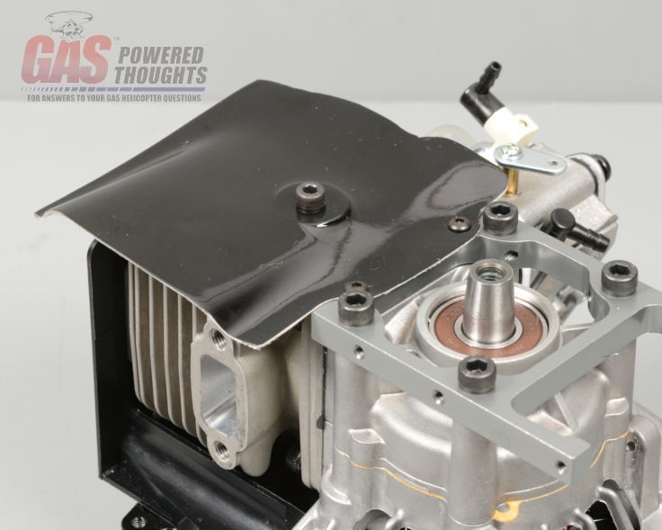 Air deflector installed Smear a drop of oil onto the angled end of the crankshaft and then place the clutch hub over the end of the crank as shown. Install a piston stop into the spark plug hole and then tighten the mount bolt shown using thread lock. NEVER hold the flywheel side of the motor when tightening up the clutch or its mount. Doing so can twist the multi-piece crankshaft 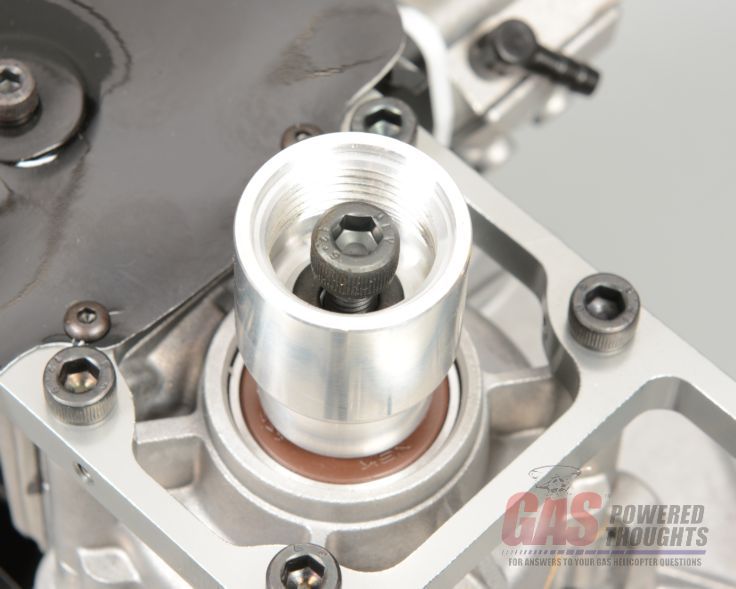 Clutch hub install Once the clutch hub is installed, the clutch will thread into it as shown 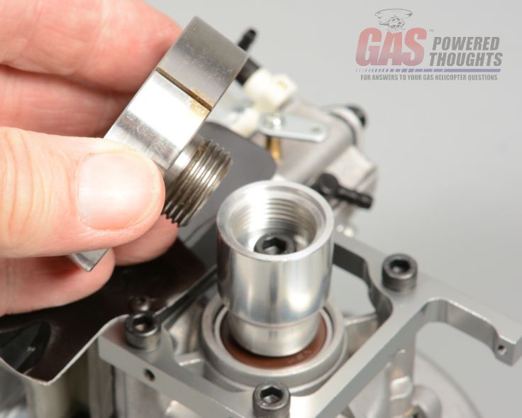 Clutch install position Here you can see the clutch fully installed. You can use thread lock on this if you want, its reverse threaded though so its not going to come out 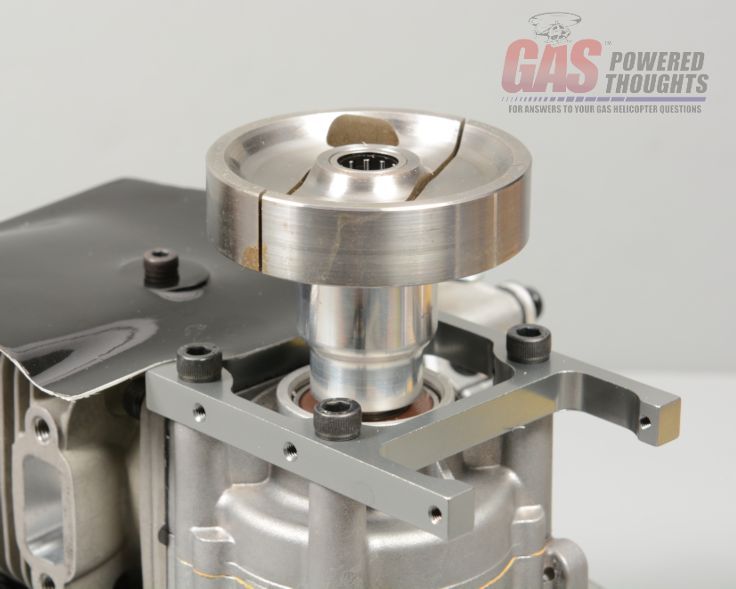 Clutch installed The kit includes an aluminum throttle control arm as shown. Its not mandatory to use it but its a nice part so its your option Install the control ball, retaining nut using thread lock and thread in the set screw for now 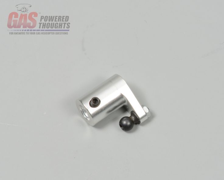 Carb arm parts Remove the stock carb control arm by removing the screw shown and lift off the plate. 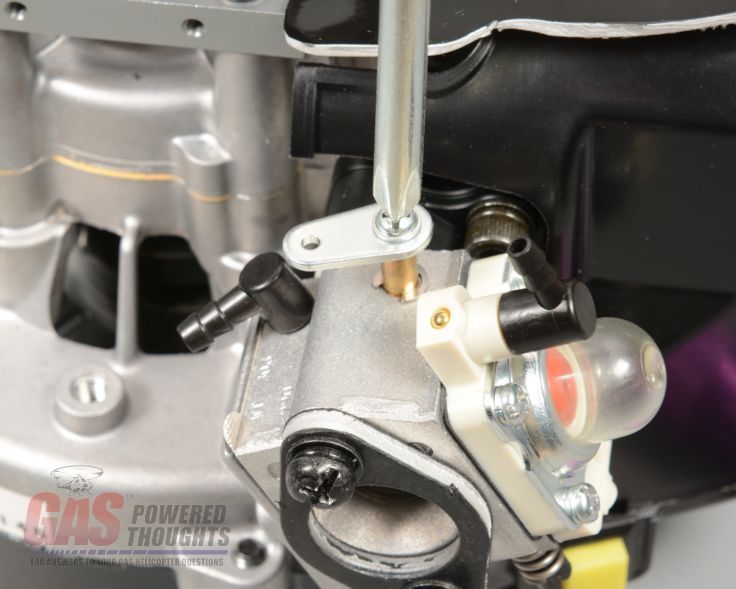 Remove stock carb arm The included control arm is designed for an older version of the walbro carburetors. If you find that it won't fit over the carb shaft you'll need to drill it out as shown. For the Walbro WT990 you'll need a 3/16" drill 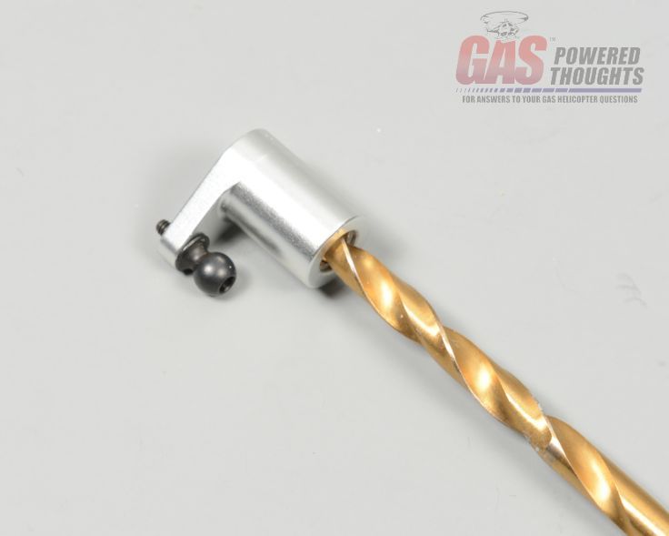 Carb arm must be drilled Now slip the control arm over the carb shaft as shown. Put some thread lock on the set screw, install it and lightly tighten it. Now move the control/arm throttle around so that its movement is roughly centered. The throttle movement is about 60 degrees. When viewed from above, you want the control arm to move about the same distance from fully closed to center as it does from fully open to center. Once you have this set, tighten the set screw Make sure before you do this that you've backed out the "idle"screw underneath the carb so that the throttle will have full throw 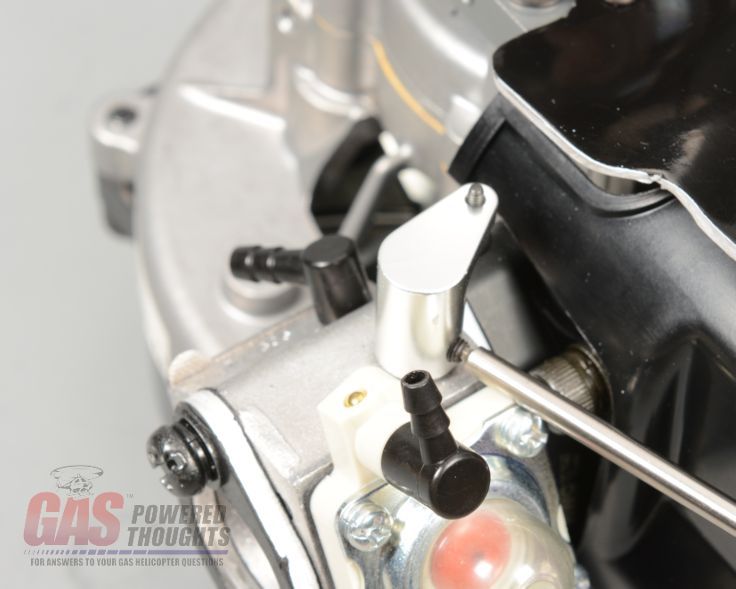 Install new carb arm The way the bottom plate is made, you cannot install an engine with a kill switch protruding as it hits the plate. You have two choices:
On this conversion I'm using the HWC EI engine and the kill switch serves no purpose so I'm going to plug the hole First remove the fan shroud by removing the two phillips head screws at the top of the shroud and the 4 - M5 bolts that hold the shroud on. Regardless these four bolts are going to be replaced with longer ones [IMG]https://i1305.photobucket.com/albums/s548/gaspoweredthoughts/HWC%20T700%20 RC%20Conversion/Engine%20Preparation/removefanshroudlr_zps008781c3.jpg[/IMG] Remove fan shroud On the EI system the switch simply pops out. 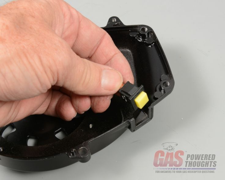 Remove kill switch I made a plug for this hole out of scrap graphite that simply slides into the place of the kill switch as shown 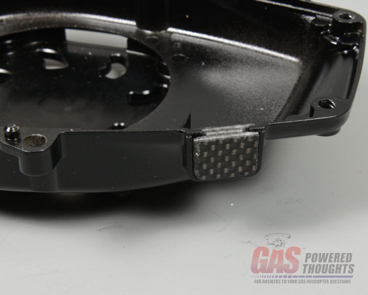 Plug for kill switch hole re-install the two phillips head screws that connect the metal fan shroud and the plastic cooling shroud. Now you can put the bottom plate on the engine. It should be oriented as shown 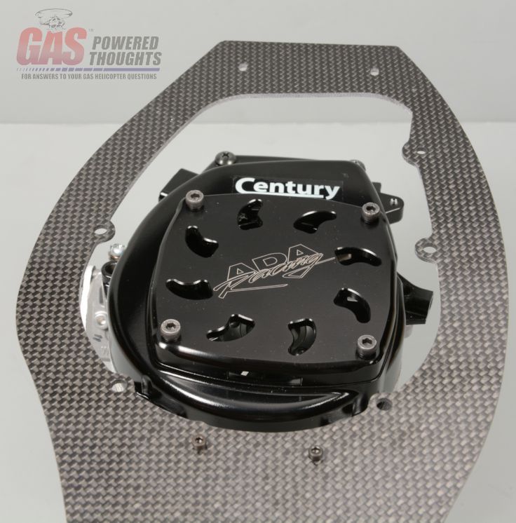 Bottom plate orientation Mount the bottom plate to the engine using the four longer M5 bolts included as well as the M4 bolt included. Use thread lock and fully tighten. This is the only conversion I've ever seen that uses that M4 bolt lug on the fan shroud 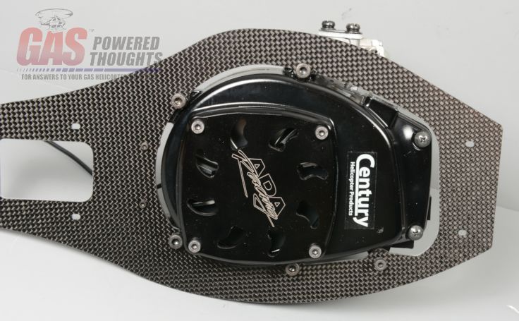 Bottom plate installed At this point the basic engine preparation is completed. Set it aside for later installation into the chassis. 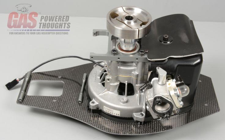 Engine preparation complete Next Step Chassis Assembly Last edited by carey shurley; 05-27-2020 at 01:12 PM.. |
|
|
|
|
08-25-2013, 10:20 AM
|
#4 (permalink) |
|
Registered Users
Thread Starter
Join Date: Apr 2004
|
Main Chassis
Time to get going on the main chassis assembly. Here are the parts/pre-assembled components that will be combined in this step. Some of the parts are from the donor model and the remainder are from the conversion kit 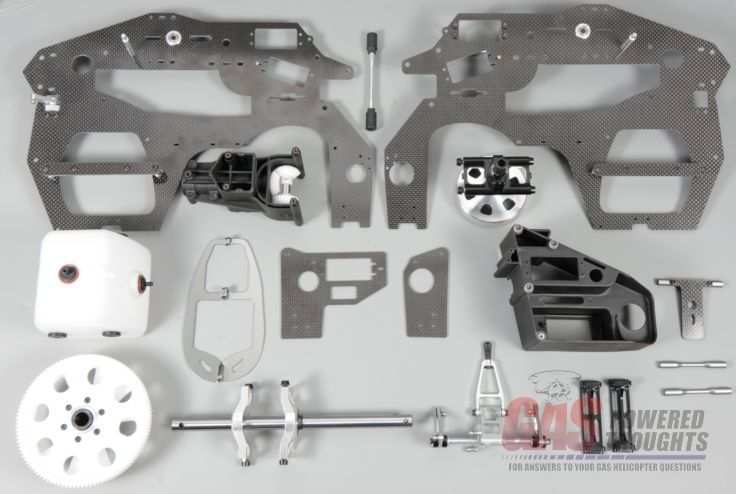 Chassis Components Start by installing the major components onto one of the frame sides, I've used the left side. Install the:
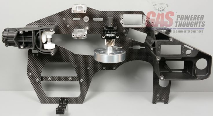 Major components installed on left frame These are the bolts used. At this point don't fully tighten or use thread lock on these 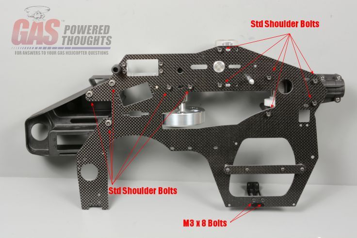 Left frame bolts required The rear holes on the main bearing blocks are not sized to use the shoulder bolts. Since the original Trex 700 only uses two bearings on the mainshaft, the conversion includes a brace to better stiffen the frame to prevent drivetrain flex. Mount this brace as shown using the included bolts. Don't use thread lock or fully tighten at this point 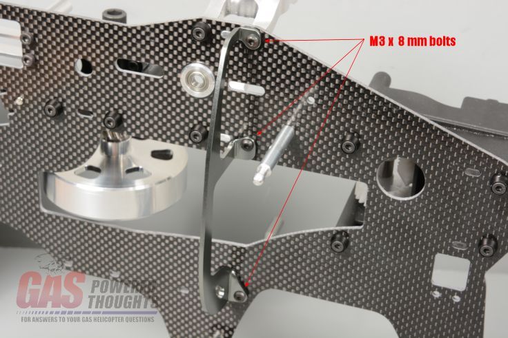 Left Frame brace installed The bottom of the brace mounts to a new rear frame spacer as shown Rear frame spacer installed The front lower frames use doublers to make them more stiff. On the left side you'll use the doubler of this shape and mount it in this orientation  Left frame doubler orientation When you bolt on the left doubler, you'll also be attaching these components 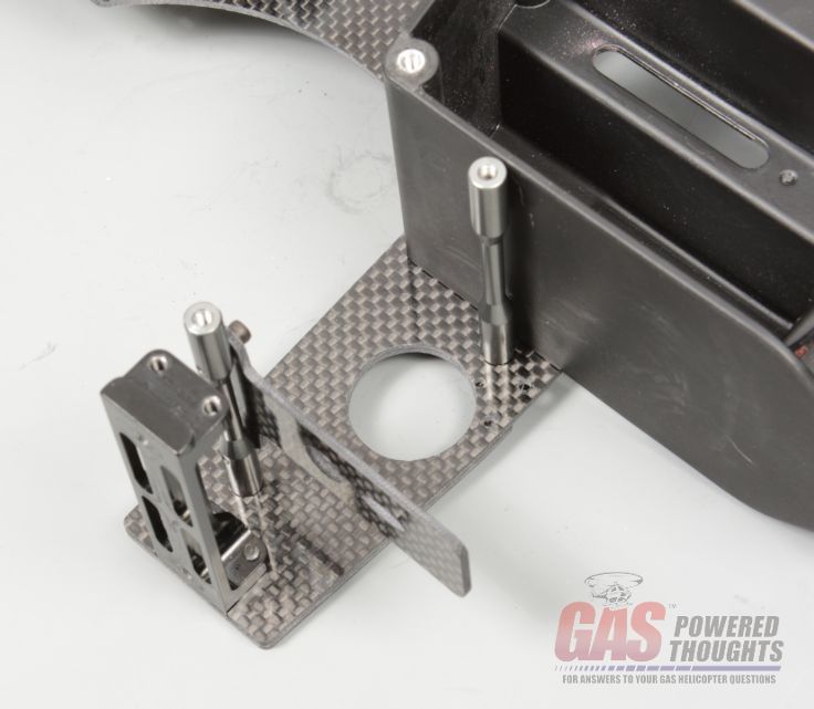 Components for left doubler install Here are the bolts lengths. Don't fully tighten or thread lock these yet 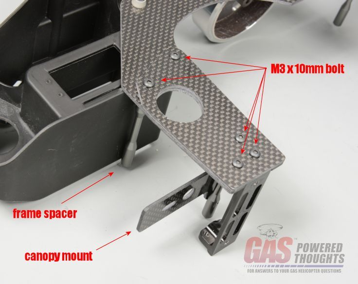 Left frame doubler installed Slip the elevator control shaft through the frame bearings as shown. This is from the donor model 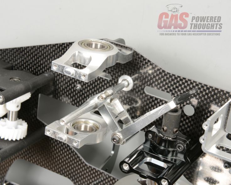 Install elevator control shaft Install the previously assemble fuel tank into its cavity on the frame. The rubber isolators on the tank will engage with the locknuts on the tank retainer. You may need to slightly rotate each isolator so that the lock nut on the retainer plate slips correctly into the five-sided hole on the isolator 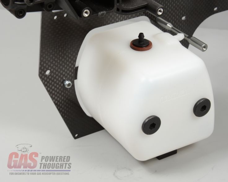 Install fuel tank Now you can install the right frame side. Set it onto the previously assembled left frame and bolt it together in the same way as the left frame. No thread lock yet and don't tighten them all. Don't forget to align the fuel tank isolators on the right side of the tank so the seat into the mount bolts on the right frame retainer. 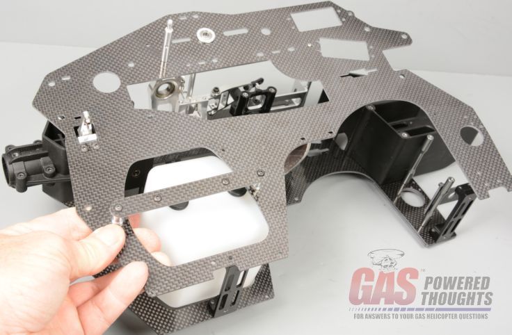 Right frame orientation There is a frame doubler for the right frame as well. Before you install it on the frame first install the front servo nut for the throttle servo  Right doubler front servo nut it is held in place by this screw. This can be fully tightened but no need to overtighten 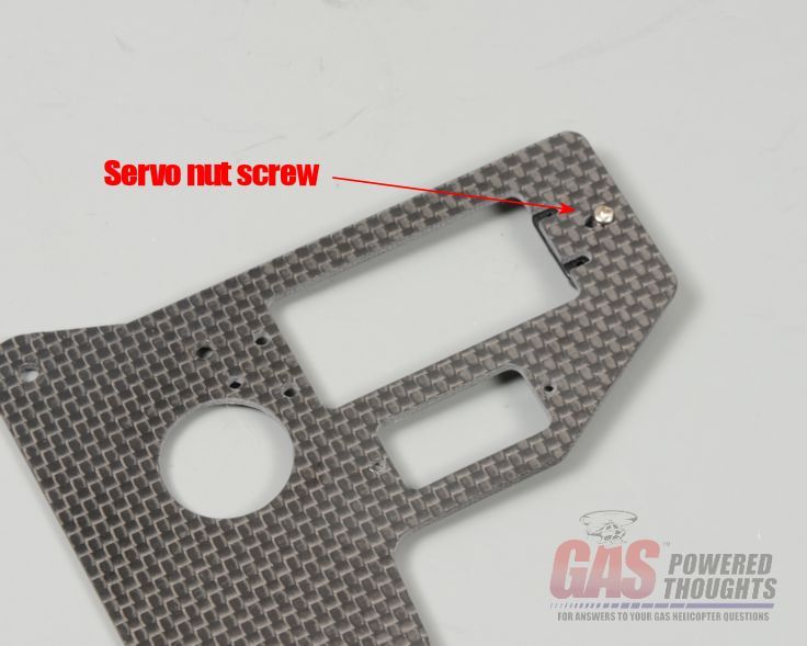 Servo nut retainer screw The right doubler is installed as shown, the bolts will be the same as on the left side with the exception of this screw 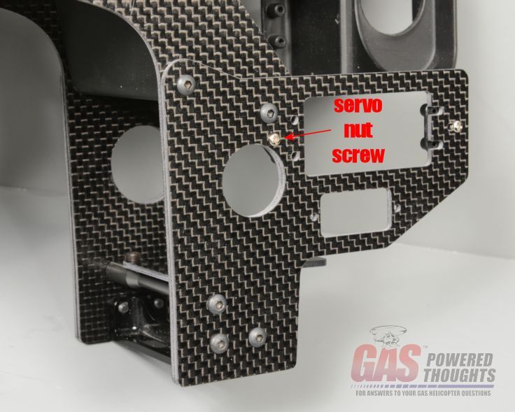 Right doubler installed which will be used to install the rear throttle servo nut as shown 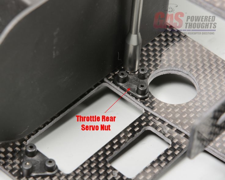 Throttle servo rear nut At this point the right frame is installed on the chassis but the bolts aren't tightened yet 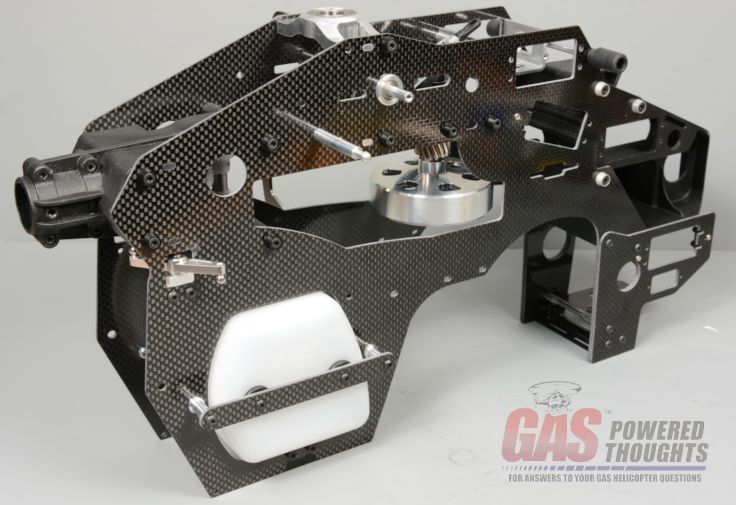 Right frame installation completed Slide the main shaft into main bearing blocks as shown. Now you can thread lock and fully tighten every bolt on both frames EXCEPT the four bolts on the clutch bearing block. Leave those loose for now 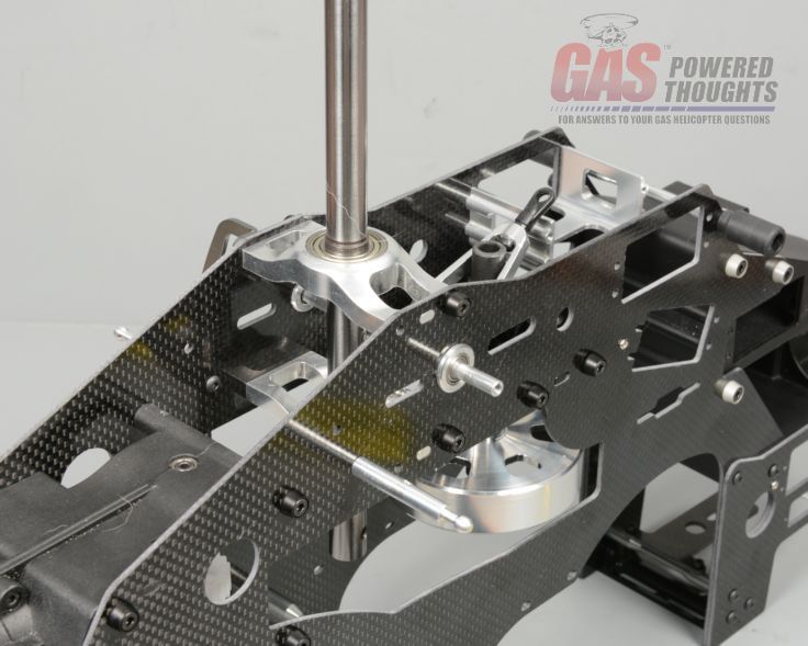 Main shaft installed Install the main gear onto the mainshaft and tighten its retaining bolt. Now install the right frame brace as shown using the same bolt pattern as was on the left frame. Use thread lock and fully tighten 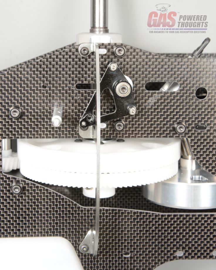 Main gear installed This conversion supports multiple gear ratios depending on the pinion size. This is why the mount holes for the clutch bearing block as well as the engine mount holes are all slotted. Before installing the engine set the main gear mesh which will properly position the clutch for your chosen gear ratio. The final step here is to set the main gear mesh. Helical gears don't require lash so using your thumb, push the pinion gear on the clutch into the main gear. Doesn't require much pressure just make sure its seated. Now fully tighten the four bolts on the clutch bearing block using thread lock 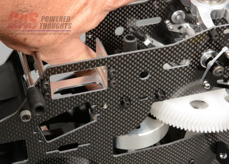 Set gear mesh At this point the central chassis assembly is completed Next Step Install Engine Last edited by carey shurley; 05-27-2020 at 01:13 PM.. |
|
|
|
|
08-25-2013, 10:54 AM
|
#5 (permalink) |
|
Registered Users
Thread Starter
Join Date: Apr 2004
|
Engine Installation
In this step we'll combine the chassis just built and the engine pre-assembly done earlier. Combining the parts is very simple, set the engine assembly on a flat surface and slip the chassis over the top of it as shown. Be careful to not pinch the ignition or EI trigger wires between the frame spacers. 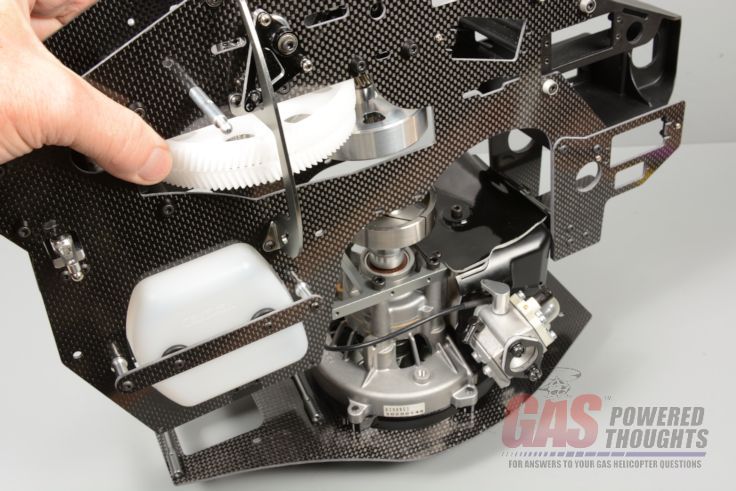 Chassis/Engine Installation orientation The engine is held in by the six M3 x 10mm bolts provided. Install them as shown but don't fully tighten them yet 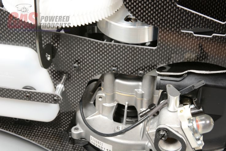 Engine mount bolts With the spark plug out of the motor, use a spin starter and spin the motor over. This will act to align the clutch and the engine assembly. Now you can thread lock and fully tighten the six engine mount bolts 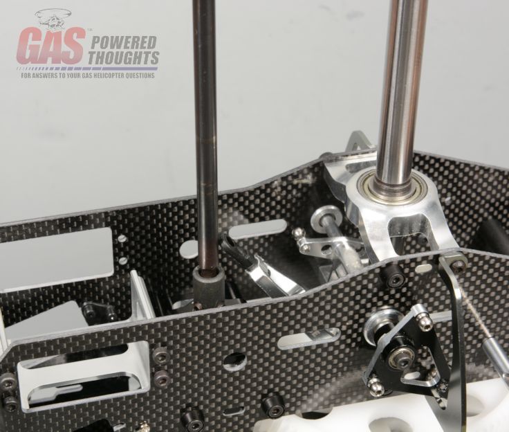 Engine spin alignment Install the four m3 x 8mm bolts that hold the rear of the engine plate to the chassis. Use thread lock. Also tighten the four bolts that hold the frame spacers previously mounted to the bottom plate. Use thread lock. 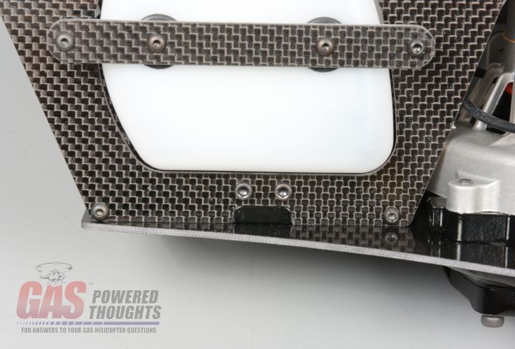 engine plate bolts At this point the engine is installed into the chassis. Make sure you're tightened every bolts using thread lock. Note how far the air deflector extends past the chassis frame 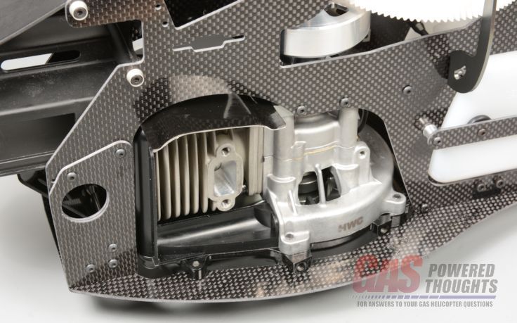 Engine installed Next Step Landing Gear Install Last edited by carey shurley; 05-27-2020 at 01:14 PM.. |
|
|
|
|
08-25-2013, 10:59 AM
|
#6 (permalink) |
|
Registered Users
Thread Starter
Join Date: Apr 2004
|
Install Landing Gear
Now the landing gear goes on the chassis assembly. You'll need the complete landing gear from the original donor model. This conversion includes some standoffs and longer bolts. The standoffs are needed for ground clearance if you intend to pull start your engine. If as in this conversion you remove the pull starter and don't intend to use it at all, then you don't need these standoffs 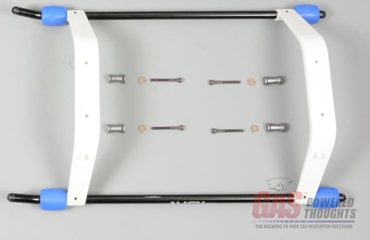 Parts for landing gear installation If you are going to use the standoffs, they install using the included longer M3 bolts. They go through the landing gear as shown and the standoffs will sit between the LG and the chassis 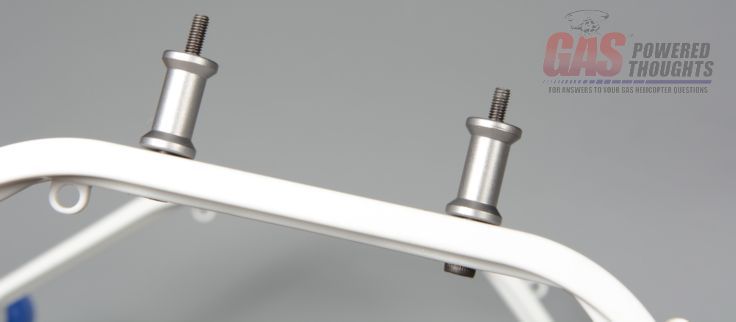 Install standoffs for pullstart version here you can see how the fit into the chassis. Install with thread lock and fully tighten 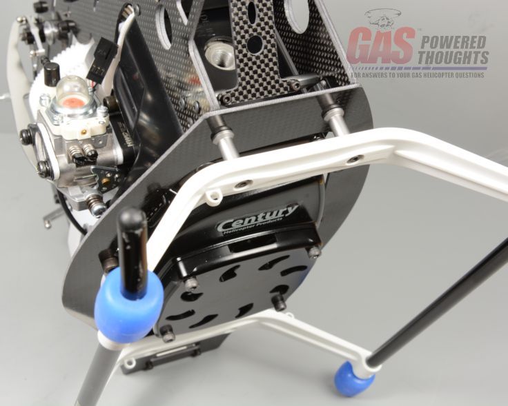 Install landing gear with standoffs - pull start version With the landing gear installed with the standoffs, you can see how it improves ground clearance 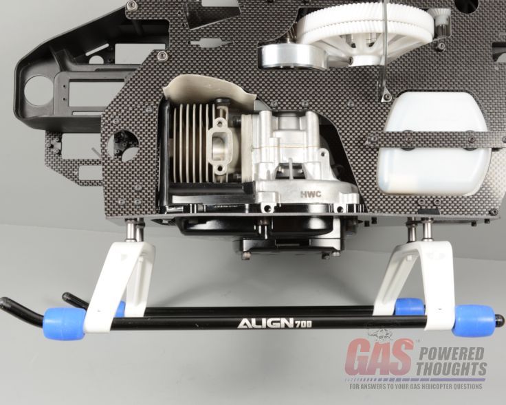 Landing gear installed - pullstart version If you don't care about pull starting, leave the standoffs out and just use the original bolts to mount the landing gear with thread lock as shown 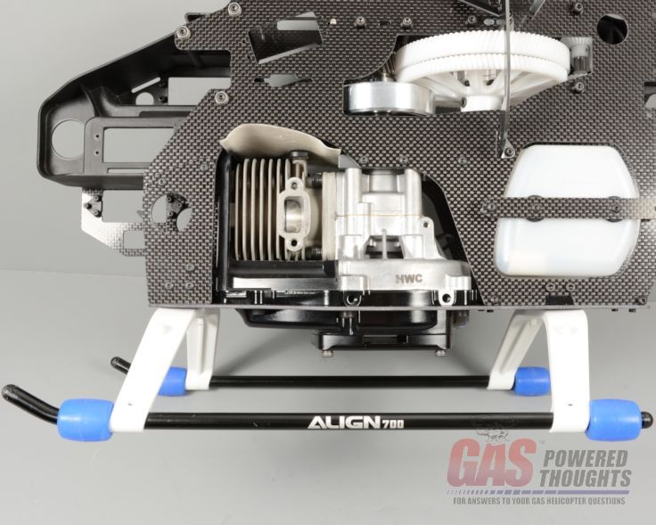 Landing gear installed - non pull start version Next Step Install Rotor Head Last edited by carey shurley; 05-27-2020 at 01:14 PM.. |
|
|
|
|
08-25-2013, 11:00 AM
|
#7 (permalink) |
|
Registered Users
Thread Starter
Join Date: Apr 2004
|
Rotor Head
Nothing unusual about these steps. First slip the swashplate from the donor model over the mainshaft and connect the control rods to the bellcranks. No adjustment should be needed from the original donor model setup 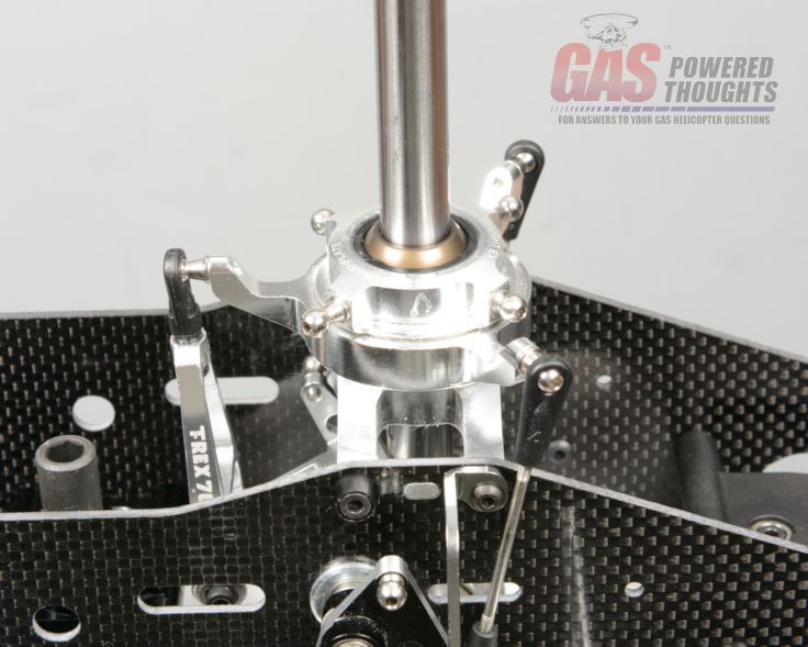 Install swashplate Install the rotor head onto the main shaft and connect the control rods. Make sure you thread lock it together 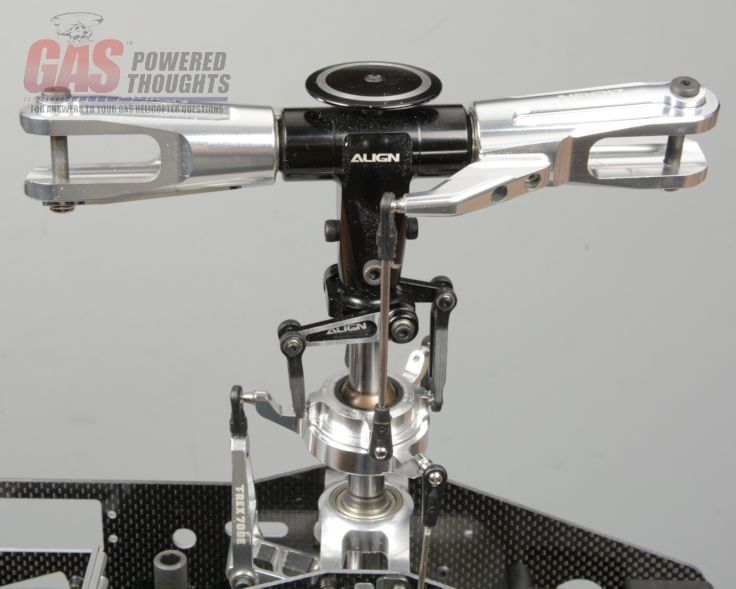 Install rotor head rotor head is now installed Next Step Install Tail Boom Last edited by carey shurley; 05-27-2020 at 01:14 PM.. |
|
|
|
|
08-25-2013, 11:03 AM
|
#8 (permalink) |
|
Registered Users
Thread Starter
Join Date: Apr 2004
|
Tail Boom
Install the assembled tail boom into the previously installed front t/r transmission. It will just slip into position. Make sure the hole in the boom aligns with the retaining pin bolt hole. Then install the front boom retainer bolt and tighten the four bolts on the tail boom clamp 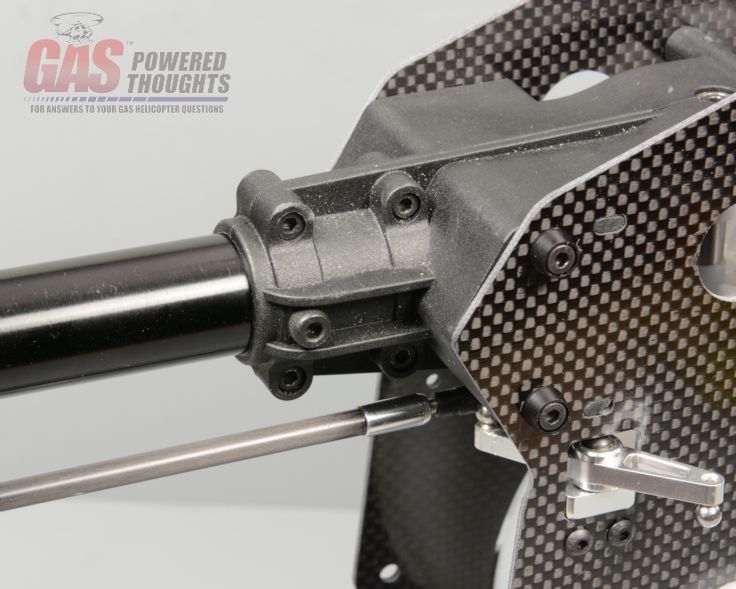 Install tail boom The boom supports install into their normal position BUT because of the way the frames are made you'll need to add some washers or spacers between the front boom support mounts and the frame. If you don't do this the support end will not fit properly onto the frame. You'll need this on both sides Boom support spacer Install both front boom support bolts using the original frame spacer and thread lock. Fully tighten. Also don't forget to check the rear boom clamp to make sure its tight on the tail boom 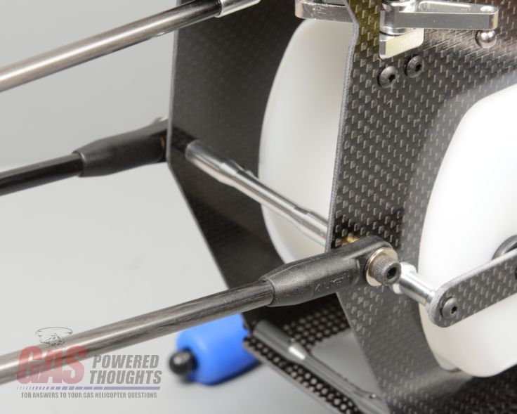 Boom supports installed Finally don't forget to re-connect the front link on the t/r control rod to the t/r bellcrank. If everything is aligned properly it should fit with no adjustment necessary. 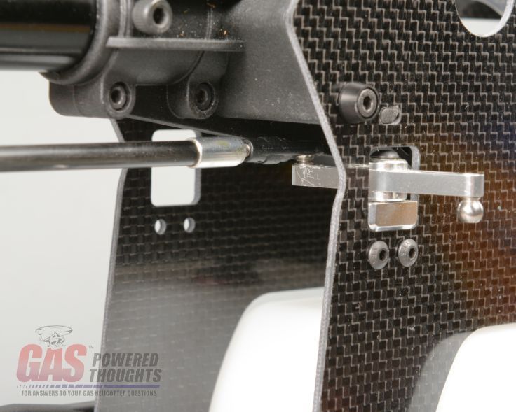 T/R control rod connected Next Step Install Electronics Last edited by carey shurley; 05-27-2020 at 01:14 PM.. |
|
|
|
|
08-25-2013, 11:04 AM
|
#9 (permalink) |
|
Registered Users
Thread Starter
Join Date: Apr 2004
|
Install Electronics
Now that the model is basically done its time to install the electronics. Nothing special about the requirements, typical as you would use in a Trex 700 Nitro model  Typical electronics needed for the setup The kit includes everything you need to mount the servos including a control rod for the throttle 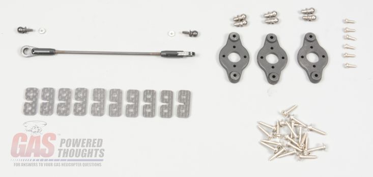 Servo mounting parts - included Century makes their own servo arms for the cyclic controls, they are a bit different from the Align wheels as they only have two mount points. They include servo balls with a much thicker base mount. I'm not sure that I've ever seen an Align ball break at the mount stud but these won't for sure 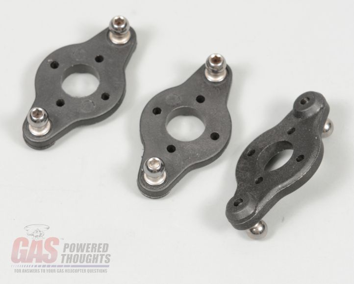 Assembled servo arms If you're wondering how they compare to the Align wheels, here you can see that they are just slightly larger in diameter than the Align wheels. They also assemble differently 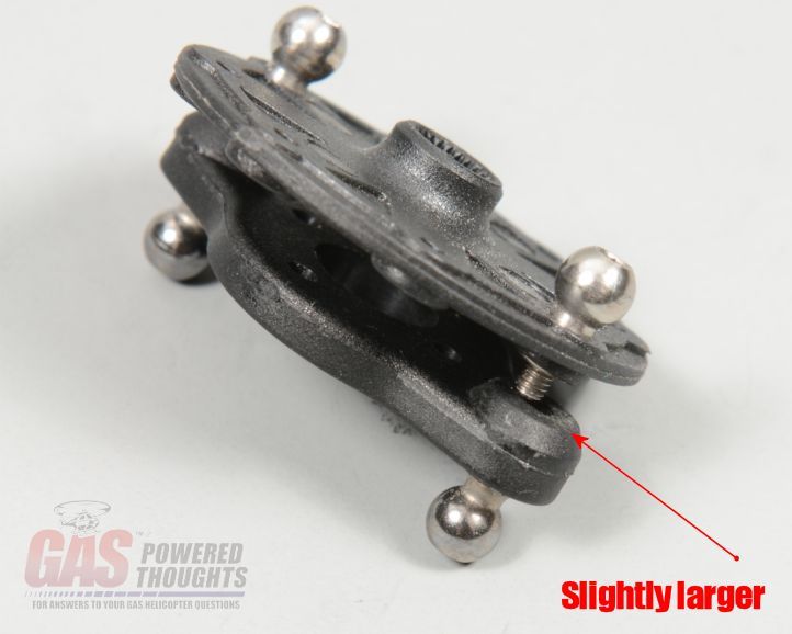 Difference between included servo arms and Align The Align arms are not specific to any radio system instead you bolt them to the small servo wheels that come with whatever servo you have. Pretty simple but you do need to have the servo wheels in their final position before you bolt these arms on 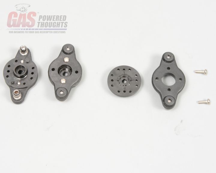 Installing servo wheels In my opinion, this area in the Align radio tray is the best place to put the EI system unit if you are using an EI system. It fits perfectly and still allows the plug wire to be routed away from everything else 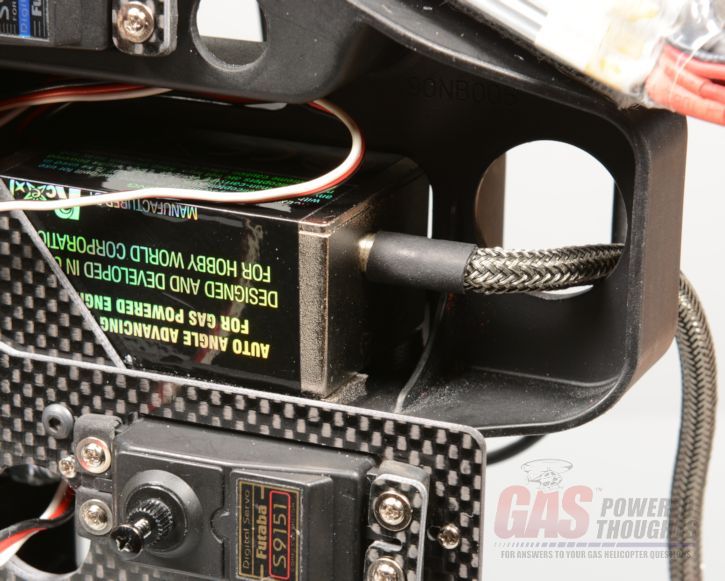 EI system location here you can see how I routed the high voltage wire through the front of the radio tray 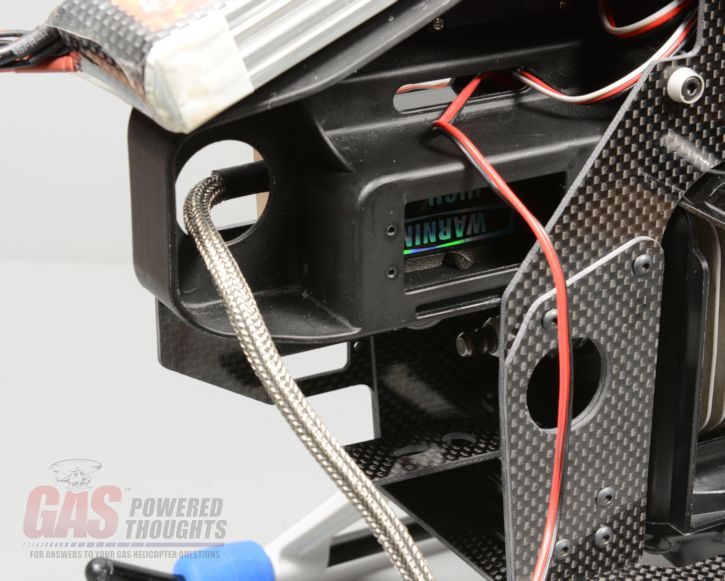 Plug wire routing There is no particular order to installing the electronics, I'll just show where they go here the left side servo, typically the aileron servo. They all mount using the small servo screws and the graphite servo retainers 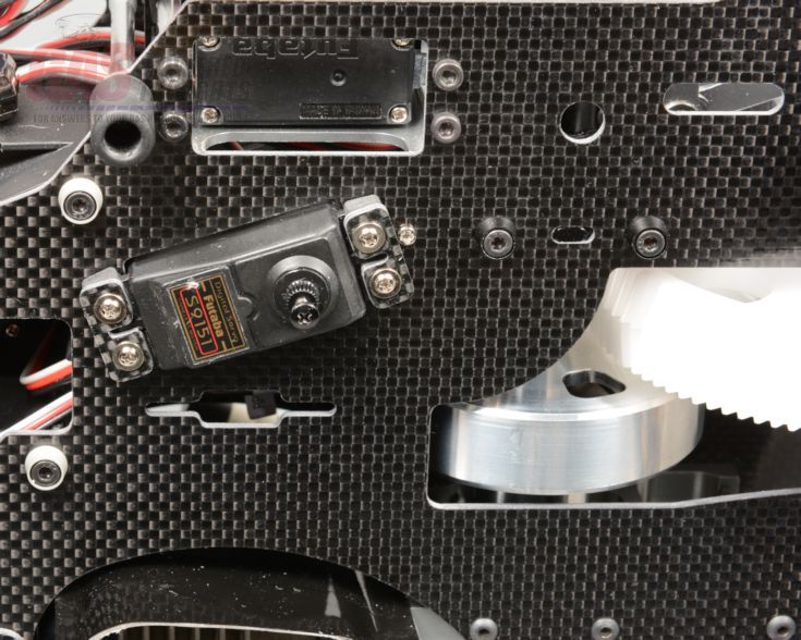 Aileron (left) servo installed And on the right side you can see the Elevator, Pitch and Rudder servos installed. If you are using a metal elevator servo tray, you'll need to use the original M2.5 bolts to mount your servo. If you are using the plastic servo tray the included screws will be fine 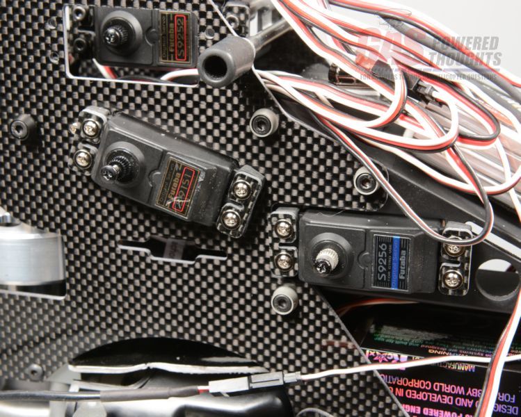 Rudder/Pitch/Elevator servos installed The throttle servo is oriented as shown. The screws thread into the previously installed servo nuts on the back of the throttle plate 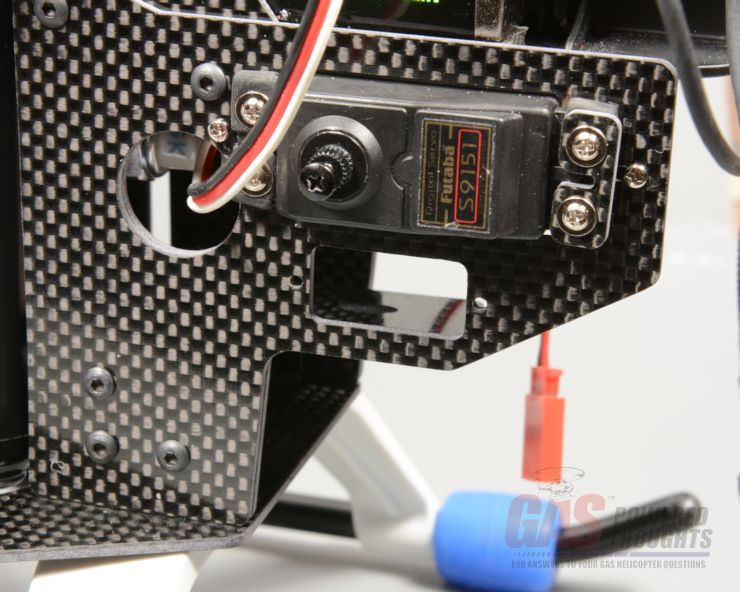 Throttle servo installed Depending on the type of FBL system you are using (or if you have a flybar they type of gyro) you'll need to mount the system. There are many places for it to go, I placed it on top of the elevator servo where it can be secured 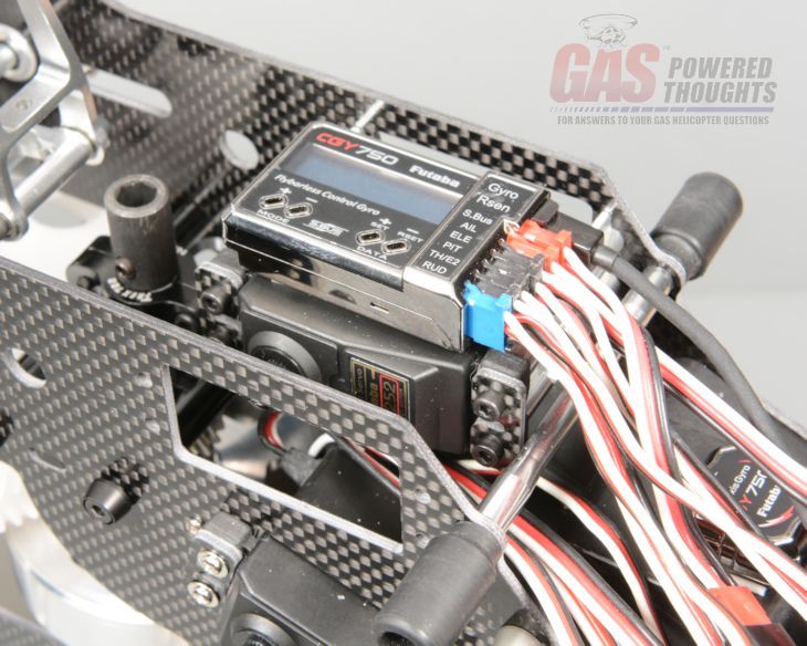 FBL controller/sensor installed The system battery should go on the front of the radio tray. Keep in mind that if you are running a shared system, the EI system draws considerable current so you should use a much larger battery than you might normally use 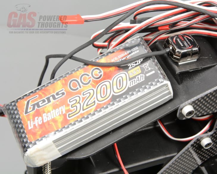 Battery installed The original control rods can be used for the cyclic controls, seen here on the aileron control 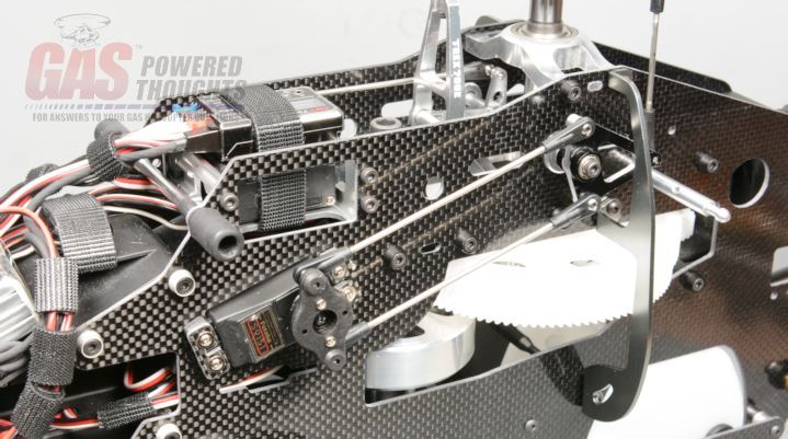 Aileron control rods installed the same is true for the pitch side 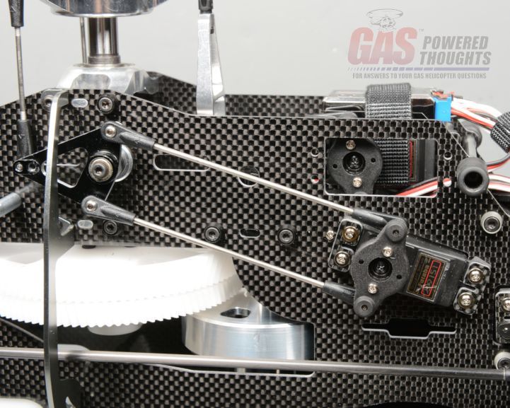 Pitch control rods installed as well as the elevator and rudder control rods 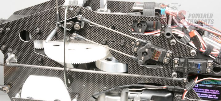 Rudder/elevator control rods installed The throttle rod is longer than normal and the kit includes one that is sized correctly 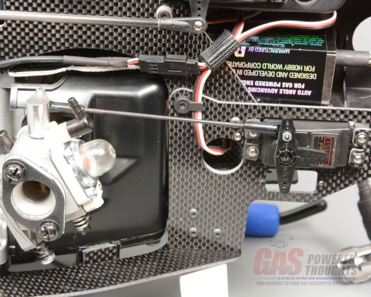 Throttle control rod installed when everything is in, it all needs to be wired up and that wiring secured. Here you can see how I did it from a left side model view 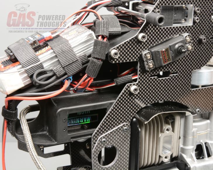 Wiring complete - left view And from the right side you can see more of the wiring routing 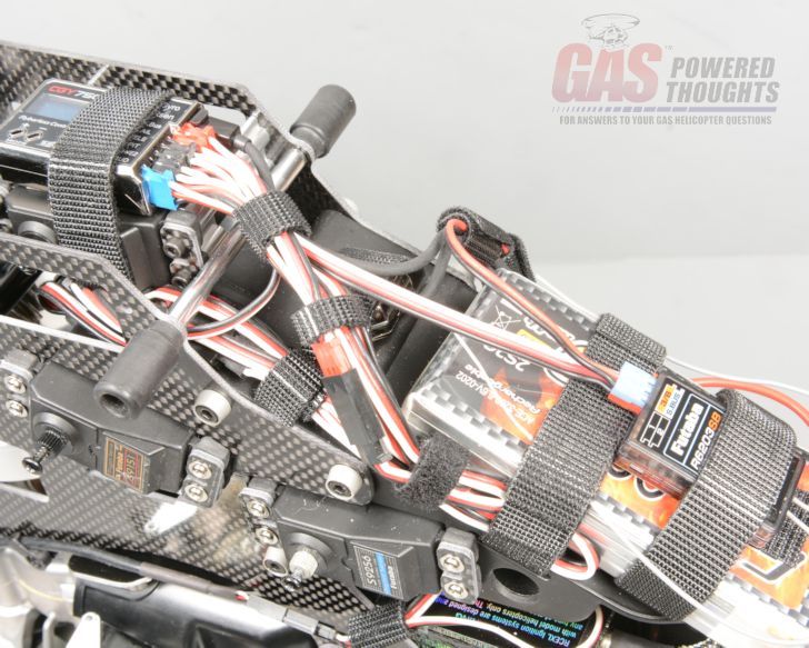 Wiring complete - right view at this point you can do the full setup in your transmitter, the remaining steps will not affect it. Next Step Model Completion Last edited by carey shurley; 05-27-2020 at 01:15 PM.. |
|
|
|
|
08-25-2013, 11:04 AM
|
#10 (permalink) |
|
Registered Users
Thread Starter
Join Date: Apr 2004
|
Final Steps to complete model
There are a few steps left to complete the model before installing the canopy start by installing the spark plug if you haven't already 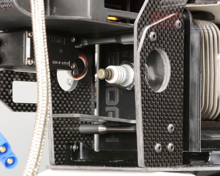 Spark Plug installed Push the plug cap over the spark plug. If you're using a magneto engine, it will route easily, if you're using an EI engine you need to work the cap around a little but it will fit as shown 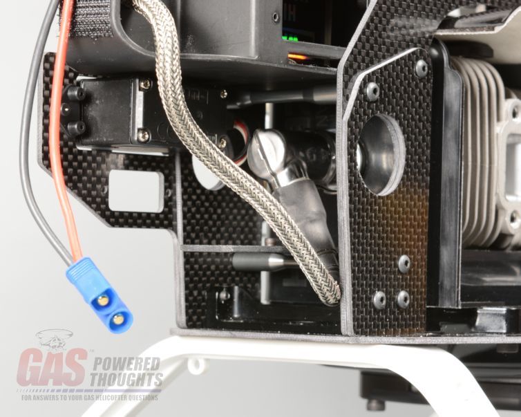 Plug cap installed Now you can plumb the fuel system. The kit comes with tubing or you supply your own. I used std tygon tubing you'll also need to vent the tank, either use a "one way" valve or create a "looped line" vent as I've shown here. This will allow the tank to vent but prevent fuel from leaking out when the model is inverted 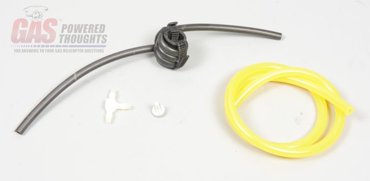 Fuel plumbing parts connect the fuel inlet line, fuel return line and the vent to the tank. Its VERY difficult to get these on the tank at this point so I removed the main gear for easy access BE VERY CAREFUL with the plastic tank fittings. They are fairly thin and can be broken so avoid side pressure 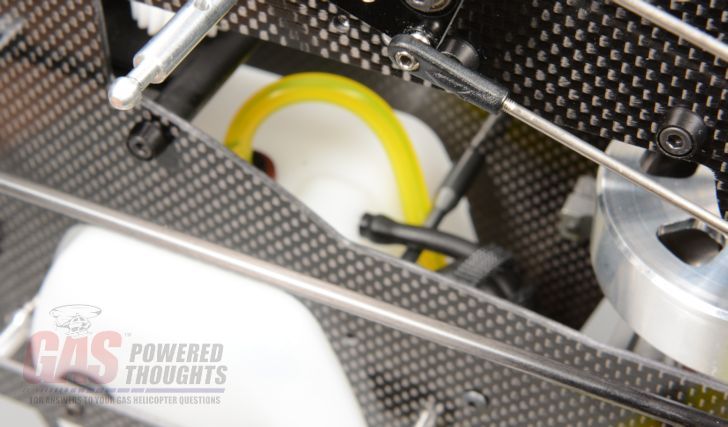 Tank side plumbed now plumb the carburetor side, you need to connect the fuel inlet and the return fitting 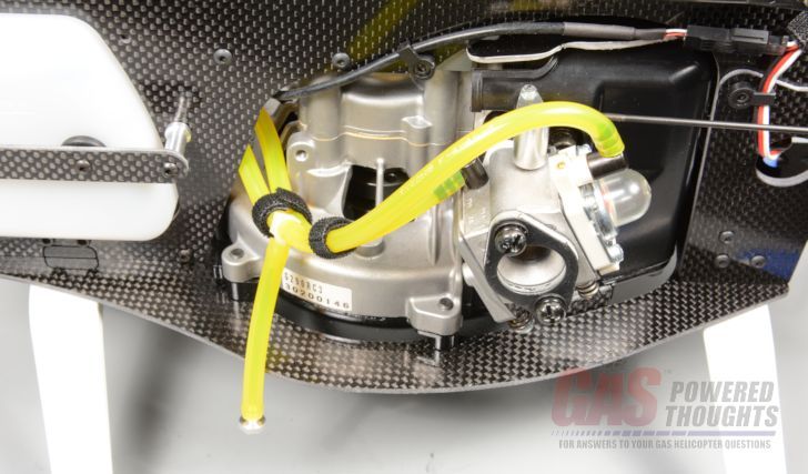 Carburetor plumbed If you are using an HWC motor, it will have come with an air filter. You definitely want to install an air filter. Now is a good time to do this, remove the carb mount bolts 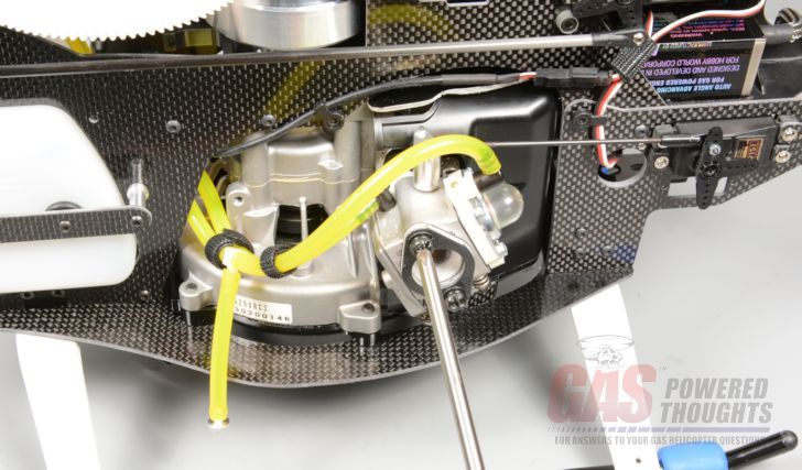 Remove carb spacer plate and then install your air filter base plate. These come in different sizes and shapes but the HWC filter base is shown. Use thread lock or RTV on these bolts to prevent the carb from coming loose 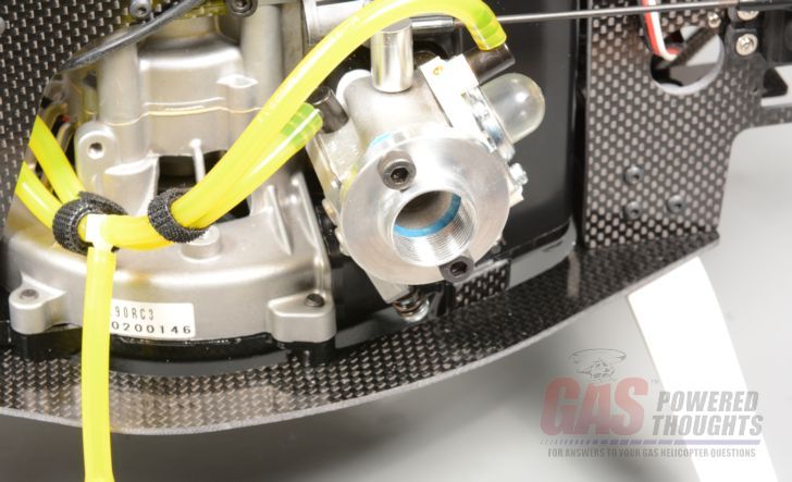 Install air filter base complete installation of the air filter. The Century filter simply threads on 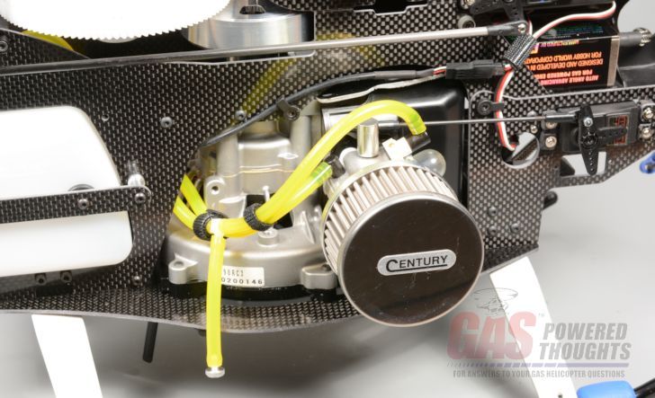 Install air filter I'd suggest you use a muffler thats quiter than the std zenoah canister muffler. Here you can see the Century Torpedo slim in position to install 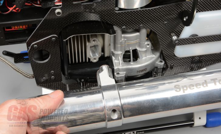 Muffler positioned for installation And with the Century muffler installed. Finally you can install other mufflers on an HWC conversion, the Hatori and/or RJX mufflers will fit easily on this conversion 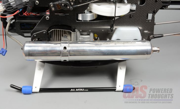 Muffler installed Wrap up the assembly by installing rotor blades. I've used 690mm Rotor Tech FBL blades. 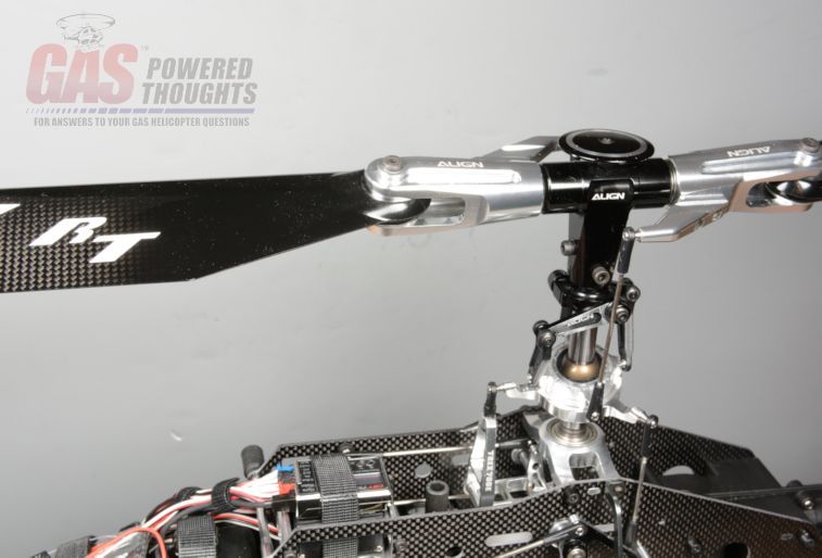 Rotor blades installed Next Step Install Canopy Last edited by carey shurley; 05-27-2020 at 01:16 PM.. |
|
|
|
|
08-25-2013, 11:05 AM
|
#11 (permalink) |
|
Registered Users
Thread Starter
Join Date: Apr 2004
|
Canopy Installation
The conversion comes with a brightly painted canopy in the style of the Century Radikal model. You can install the std Trex canopy but this one is larger. With the taller chassis the std canopy looks a bit odd. This one is more in proportion to the model the kit includes what you need to install it  Parts to Install Canopy the rear of the canopy is pre-drilled for the mount grommets, install them and apply thin CA to them inside the canopy. They will be more vibration resistent if you glue them in place.  Grommets installed The mount that holds the canopy in place is not long enough. To address this, use velcro to ensure that it can't come off. Put one piece here on the chassis mount 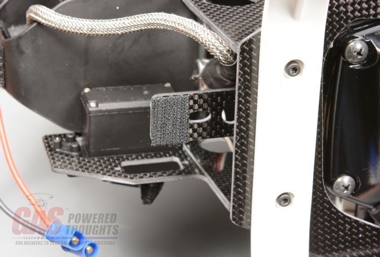 Install Velcro on mount Depending on which muffler you are going to run, you may want to slightly adjust the angle/position of the canopy. You can do this by moving the front lower canopy mount tab to the bottom of the frame spacer it attaches to. To change this at this point you'll need to remove the two bolts on the outside of the frames that hold this in place, remove it and flip it over. MAKE SURE you've chosen the position for this BEFORE you make the air deflector cutout in the canopy 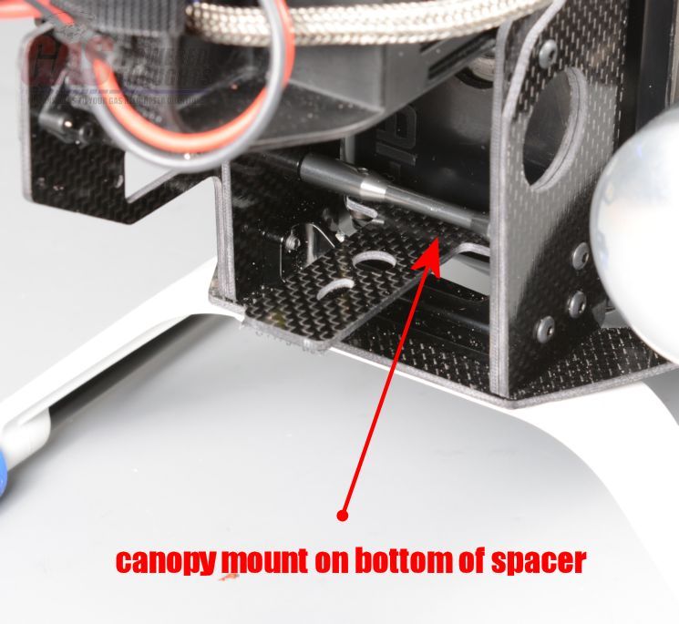 Adust position of lower canopy mount and put its matching piece here in the center bottom of the canopy 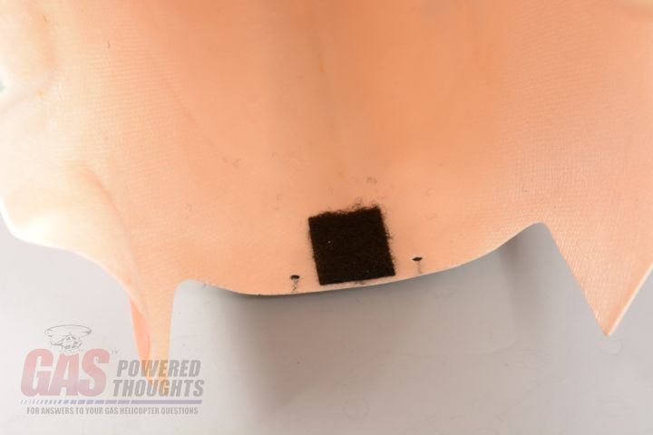 Install velcro on canopy mount the lower canopy retainer in place as shown, center it on the bottom of the canopy and mount it with the wider opening towards the chassis. You'll need to drill two small holes for the mount screws. The exact position isn't critical but you want it to be as close to the edge of the canopy as you can get it 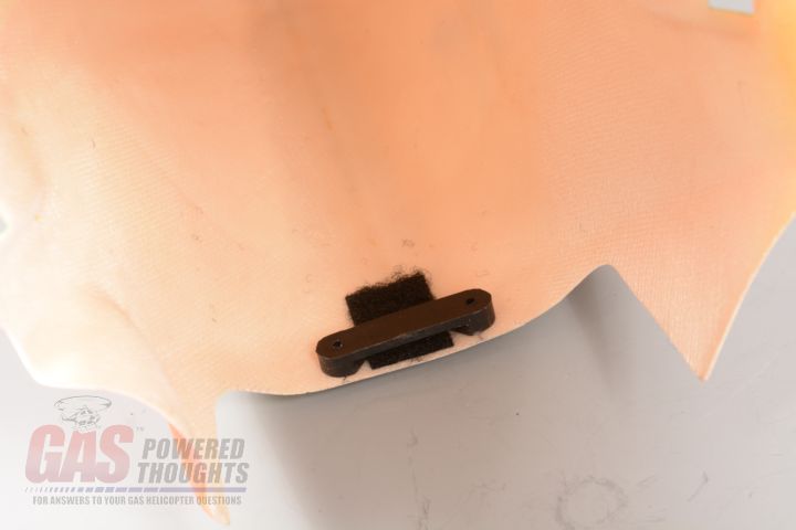 Canopy retainer installed here you can see the two screws that hold the retainer in place. Use slow CA when you install them 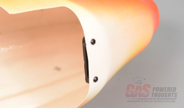 Canopy retainer screws Fit the canopy onto the model and you'll see that you need to trim it slightly to allow air from the air deflector to exit the canopy. This is the approximate shape 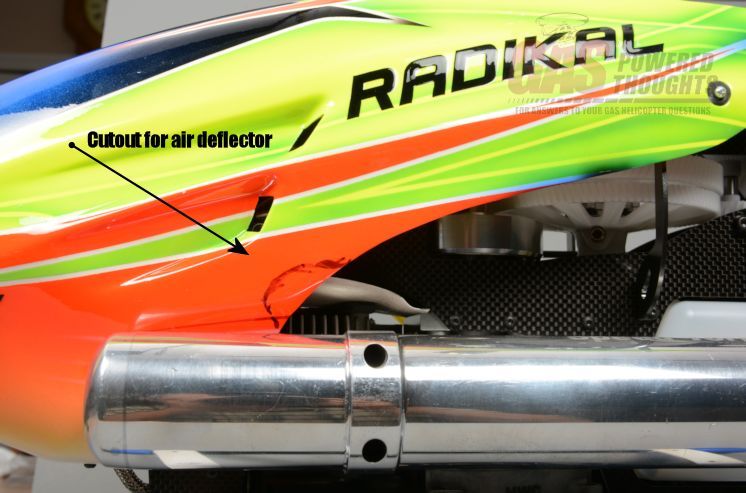 Canopy marked to trim remove the canopy and trim the small area, I used a dremel tool and a grinding wheel  Canopy with cutout here you can see how the canopy has been relieved. This is important, if you don't make this cut the hot cooling air blowing from the motor can collect in the canopy and overheat your electronics 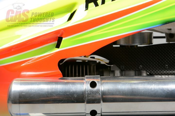 Air Deflector clearance finally here's the model with the canopy installed.  Canopy installed Next Step Model Summary Last edited by carey shurley; 05-27-2020 at 01:17 PM.. |
|
|
|
|
08-25-2013, 11:06 AM
|
#12 (permalink) |
|
Registered Users
Thread Starter
Join Date: Apr 2004
|
Well thats it, the model is complete. Here are a view different views
 Right Side - Canopy on  Left Side - Canopy on 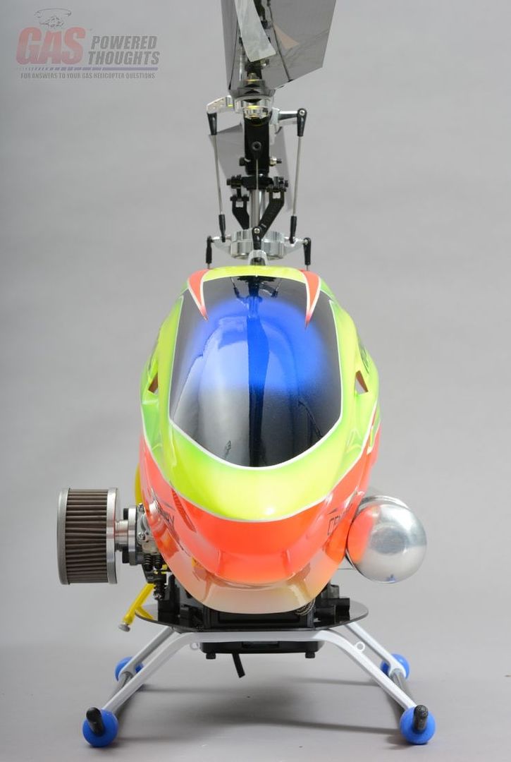 Nose on view - Canopy on 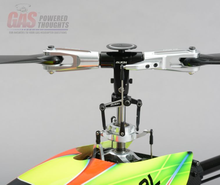 Std Align rotor head 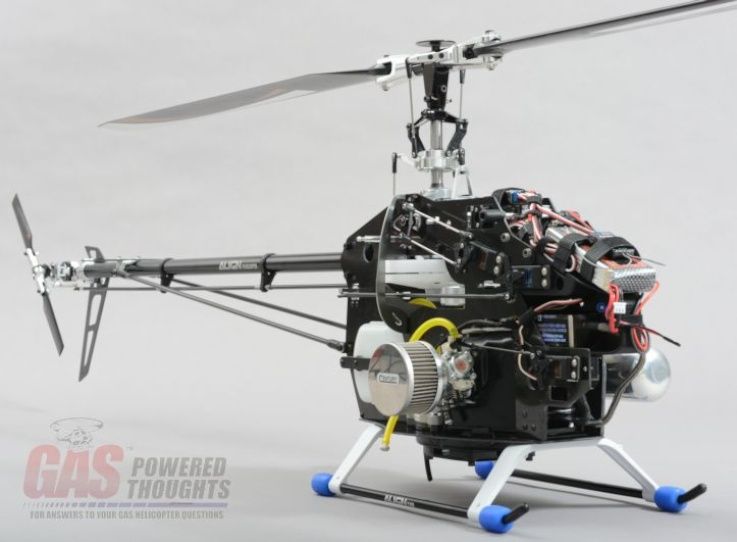 Right Side - Canopy off 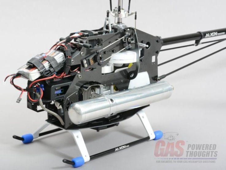 Left Side - Canopy off 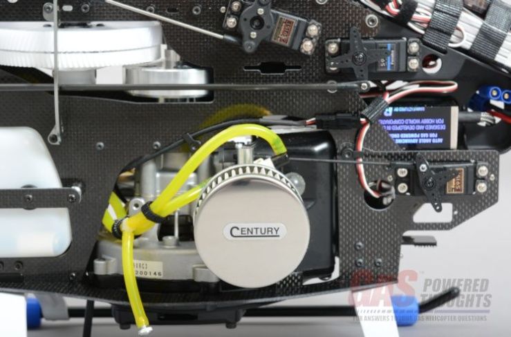 Engine closeup view Last edited by carey shurley; 05-27-2020 at 01:17 PM.. |
|
|
|
|
08-25-2013, 11:06 AM
|
#13 (permalink) |
|
Registered Users
Thread Starter
Join Date: Apr 2004
|
Build Overview
This conversion is easy, rather than do a series of build videos I made this build overview Video Narrative Last edited by carey shurley; 09-17-2013 at 06:44 AM.. |
|
|
|
|
08-25-2013, 11:07 AM
|
#14 (permalink) |
|
Registered Users
Thread Starter
Join Date: Apr 2004
|
coming soon
__________________
Carey Shurley Proprietor - Gas Powered Helicopters Last edited by carey shurley; 09-17-2013 at 06:46 AM.. |
|
|
|
|
09-17-2013, 06:45 AM
|
#15 (permalink) |
|
Registered Users
Thread Starter
Join Date: Apr 2004
|
I posted a build overview video for the conversion
|
|
|
|
|
09-21-2013, 02:47 PM
|
#16 (permalink) |
|
Registered Users
Join Date: May 2007
|
That looks more like a Radikal conversion using "Better quality" parts from Trex700....
Changing original main gear of Trex700 to lesser diameter main gear means reducing the power band of the original design.  |
|
|
|
|
02-11-2015, 09:30 AM
|
#17 (permalink) |
|
Registered Users
Join Date: Oct 2014
|
Hi,
did you ever fly that conversion? I have finished mine now. I am waiting for warmer weather that I can do my maiden flight. If you have any videos or experiences from the first flights please post them! Thanks Siegfried |
|
|
|
|
08-07-2017, 05:33 AM
|
#18 (permalink) | |
|
Registered Users
Join Date: Aug 2017
Location: Washington
|
Quote:
|
|
|
|
|

|
08-07-2017, 07:09 AM
|
#19 (permalink) | |
|
Registered Users
Join Date: Jul 2013
Location: Middle East
|
Quote:
Perhaps contact them to ensure this is still available and parts will continue for some time. |
|
|
|
|
|
08-08-2017, 07:28 AM
|
#20 (permalink) |
|
Registered Users
Thread Starter
Join Date: Apr 2004
|
it is a well done and complete conversion and retains typical Trex flying characteristics.
however they have ceased production of their helicopter lines. If you're intent on this conversion I would suggest you buy several of them for parts. Most of the parts are durable and will take a lot of abuse.......but it only takes one that you can't replace to ground the model. If your query is in regards to Kandace's model, shes a real gas helicopter enthusiast and an A&P so she takes great care of her models
__________________
Carey Shurley Proprietor - Gas Powered Helicopters Last edited by carey shurley; 08-08-2017 at 09:29 AM.. |
|
|
|
|
|
|
«
Previous Thread
|
Next Thread
»
| Thread Tools | |
| Display Modes | |


 Linear Mode

|
|


