| START HERE |
|
| Register | FAQ | PM | Events | Groups | Blogs | Calendar | Mark Forums Read |
|
|
|
Unregistered
|
||||||


| MSH Protos MSH Protos Helicopter Support Forum |
|
|
 |
|
|
LinkBack | Thread Tools | Display Modes |
 08-13-2015, 09:50 AM
|
#61 (permalink) |
|
Registered Users
Thread Starter

Join Date: Sep 2011
Location: The Netherlands
|
Here's part 1 of all the posts with revised url's:
Well, considered for months getting a Protos, I received all my components, I ended up with this setup: MSH51106 Kit Carb - kit ONLY MSH51321 Stretch kit Protos 500 - CARBON ONLY - MSH51115 Flybarless upgrade Kit MSH51335 Low flybarless hub (only stretched protos) MSH51122 Alu pulleys set MSH51135 Tail blades Orange MSH51063 MSH Scorpion HK-3026 880KV YGE 80 with built-in external governor support Mikado 04357 Mini V-Bar "Blueline" 5.3 Express Mikado 06003 VBar Software 5.3 PRO 3x MKS DS9660A+ mini size swash servo Futaba BLS251 brushless standard size tail servo Futaba R6303SB 2.4GHz FASST Micro S.Bus HV Receiver EC3 connectors Unfortunately I wasn't able to get a FBL kit, though I've seen one store which supposedly has them. However, I did manage to find an unused original YGE 80, which is out of production these days. I had it sent in to YGE, to include external governor support. I've also ordered a single Desire Power 6S1P 3000mAh LiPo and will start from there. I've replaced the stock motor shaft already with the long one from the stretch kit, using a self made tool, an arbor press and a drill press. Here's a pic with all the components: 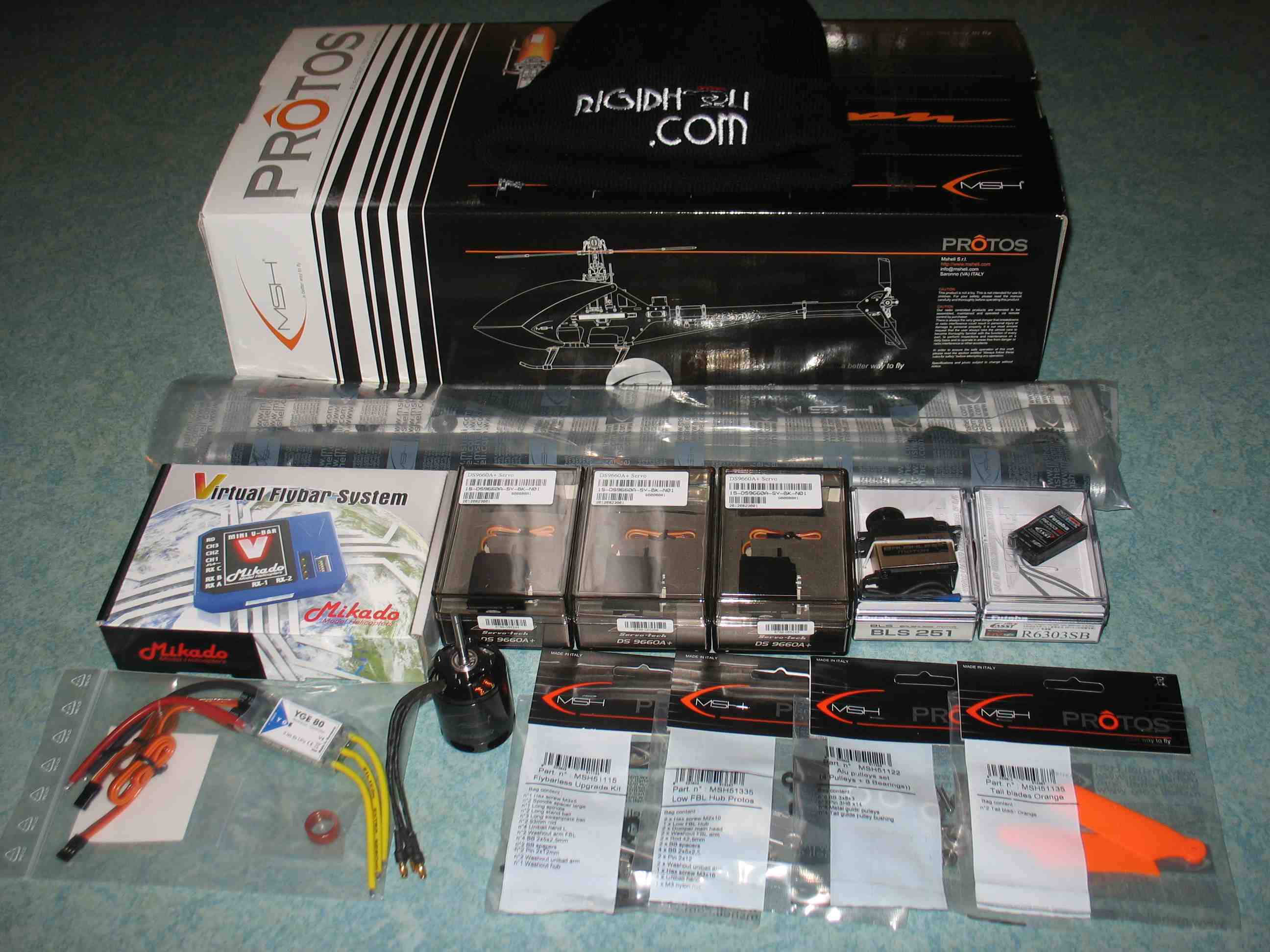 full resolution pic: http://rzavelli.home.xs4all.nl/stuff...s/IMG_2061.JPG Time to go building! Wet sanding of the carbon fibre plate parts: 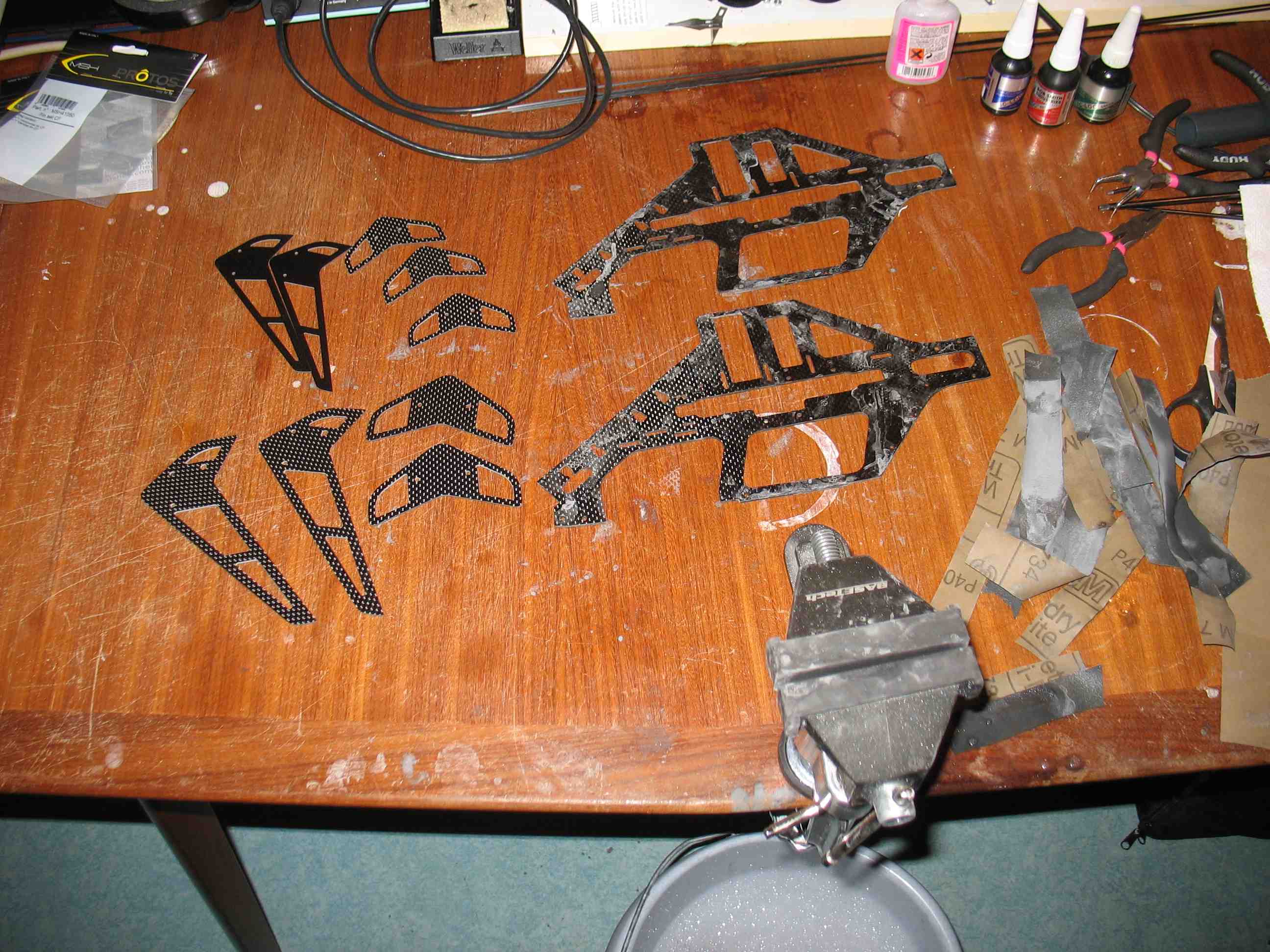 full resolution pic: http://rzavelli.home.xs4all.nl/stuff...s/IMG_2067.JPG I'm sanding some extra Protos and Mini Protos tail fins, since I seem to molest those on a weekly basis, doing retarded but funny auto's. Before continuing I've decided to clean my work bench first, placing my wrenching towel again (to prevent the bouncing of screws off the table). Table isn't planar, was growing pretty tired of screw drivers rolling off from it. 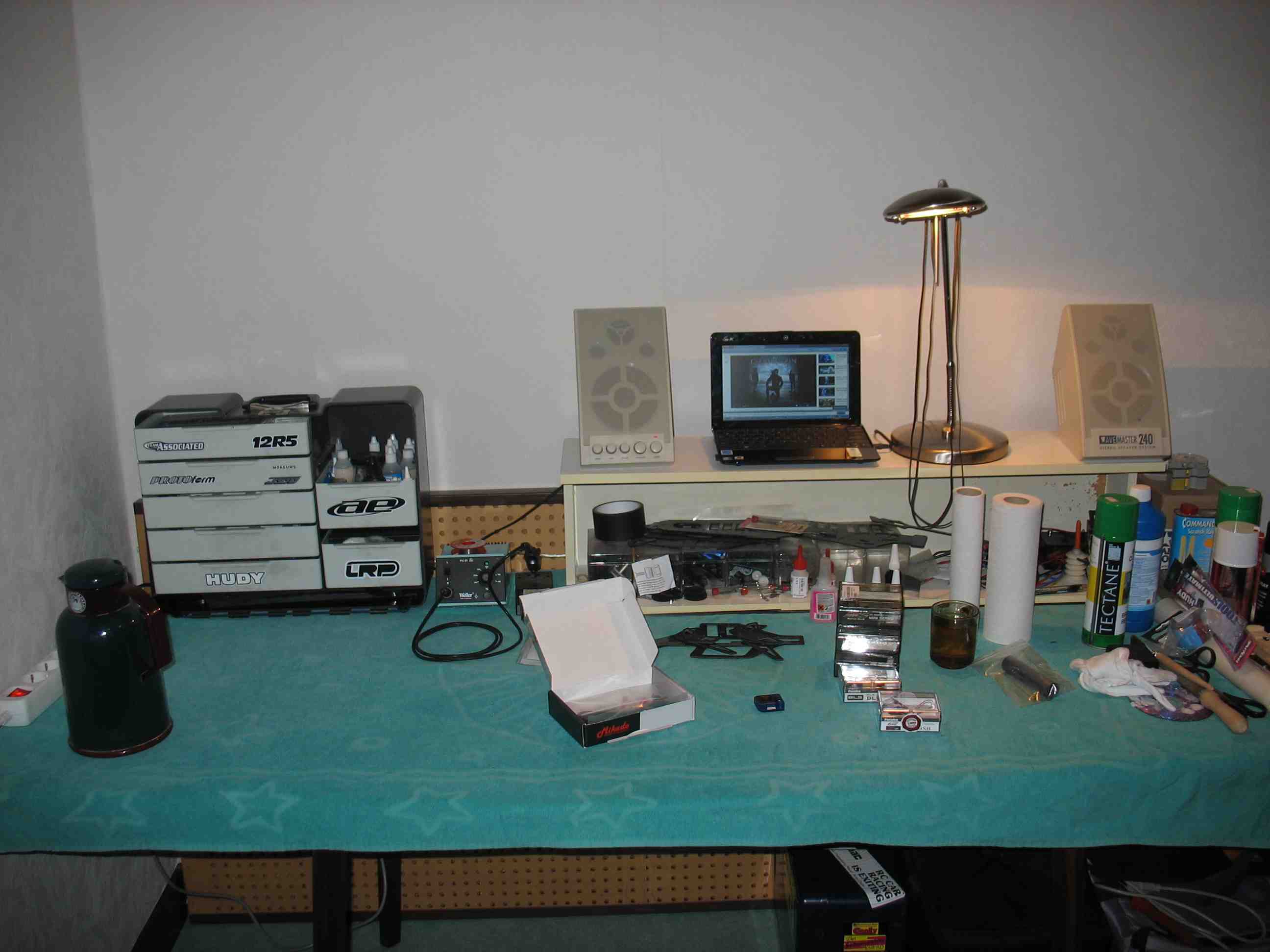 full resolution pic: http://rzavelli.home.xs4all.nl/stuff...s/IMG_2073.JPG Now it's time to center servos and prepare servo horns. I'm not sanding the planar surfaces. Wet sanding is done just to smooth the edges, feels nicer to the touch and looks better. It's an old habit from competitive RC car racing, there we would go even further with CF parts to seal them, preventing splitting: - Wet sand across the CF edges with 600 grit sand paper whilst holding in a small vice, this would round the edges. - Degrease the parts thoroughly with soapy water.This is important, since CA drying up near greasy areas will leave dirty white stains. - Apply thin CA to a cotton swab (Q-tip) and drag that around the edges to seal them. - Softly wet send the CA in the length of the edge with 1200 grit sand paper in a small vice to get an even semi-gloss finish. But anyway, for helicopters I just do the first step, no point in sealing. If you want to sand your CF part edges as well, make sure to use water, since the fibers in the CF dust are nasty. Once nested in your lungs, they stay there, forever. Hence sanding with water. Found the actual holes in the servo horns were of 1.5mm diameter instead of 2mm a few days ago (assumption is the mother of all **** ups). So during lunch break at work, I went to the shop floor. Bolted the servo horns inverted to a plank with a M3 screw and a fender washer, used a 2mm drill bit and drill press with high rpm to enlarge the existing holes. 16.5mm offset for the swash (16mm requested in the manual) 13.5mm offset for the tail (13.5mm requested in the manual) Result: 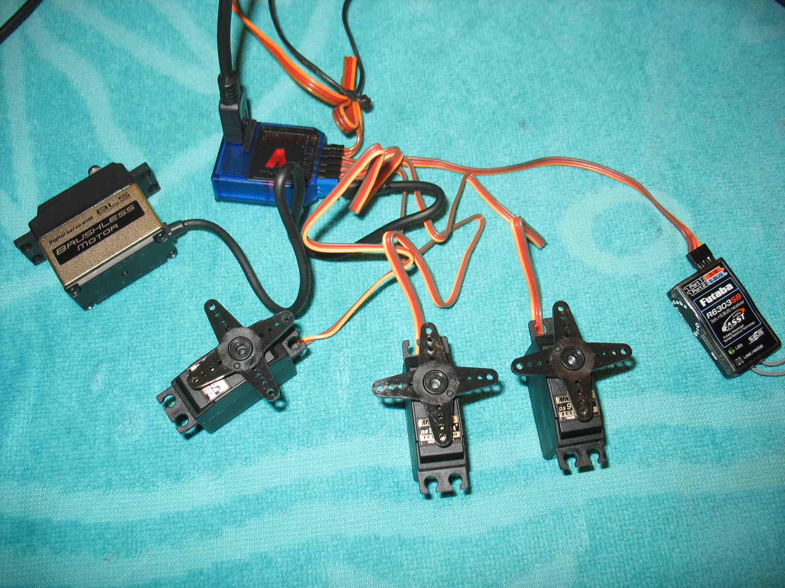 full resolution pic: http://rzavelli.home.xs4all.nl/stuff...s/IMG_2077.JPG Then the awefull job of trimming excess material, of course the end result has to look neat: 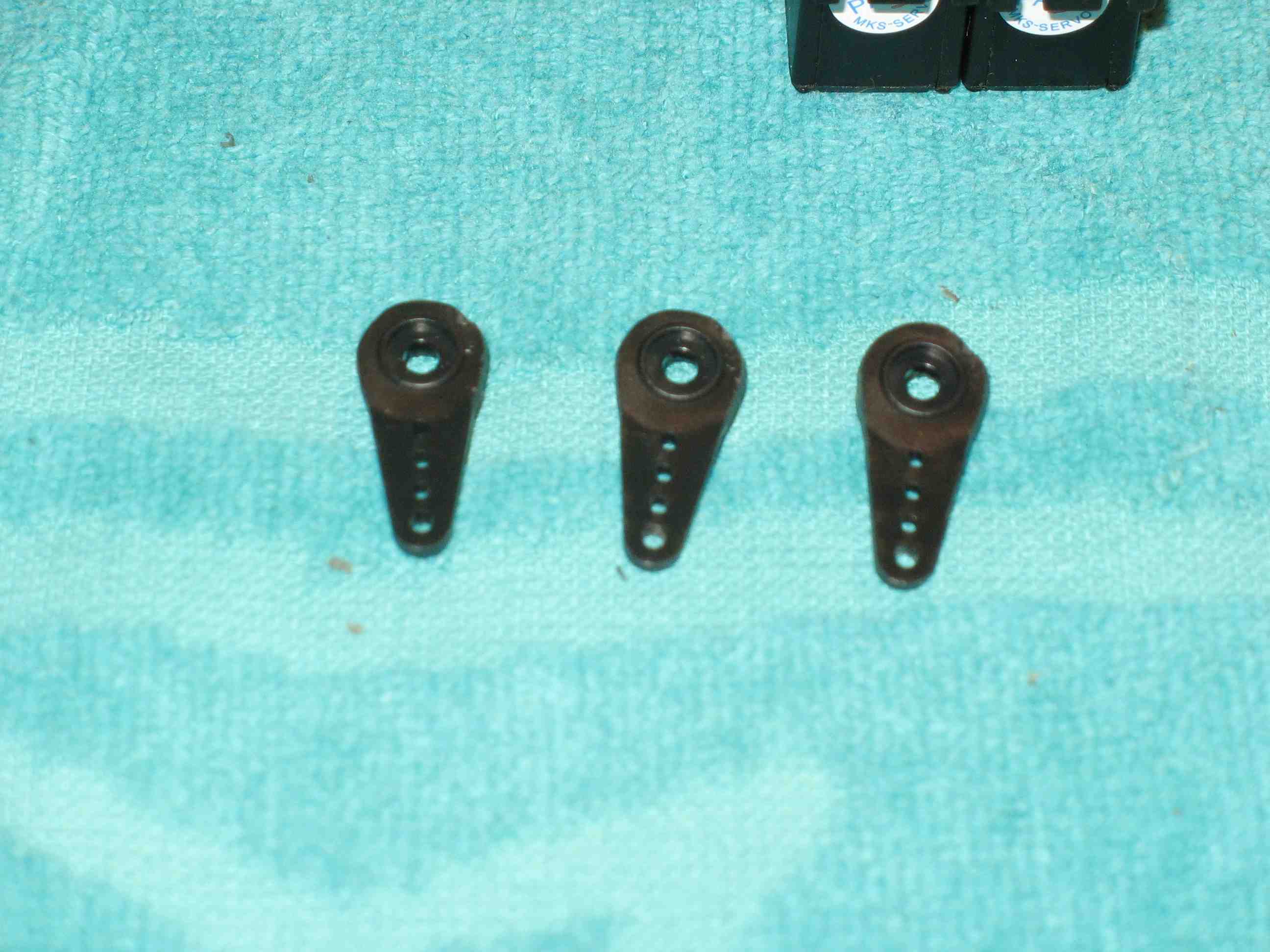 full resolution pic: http://rzavelli.home.xs4all.nl/stuff...s/IMG_2089.JPG Swash servo horns fitted and trimmed perpendicular to the servo housing in the V-Bar software: 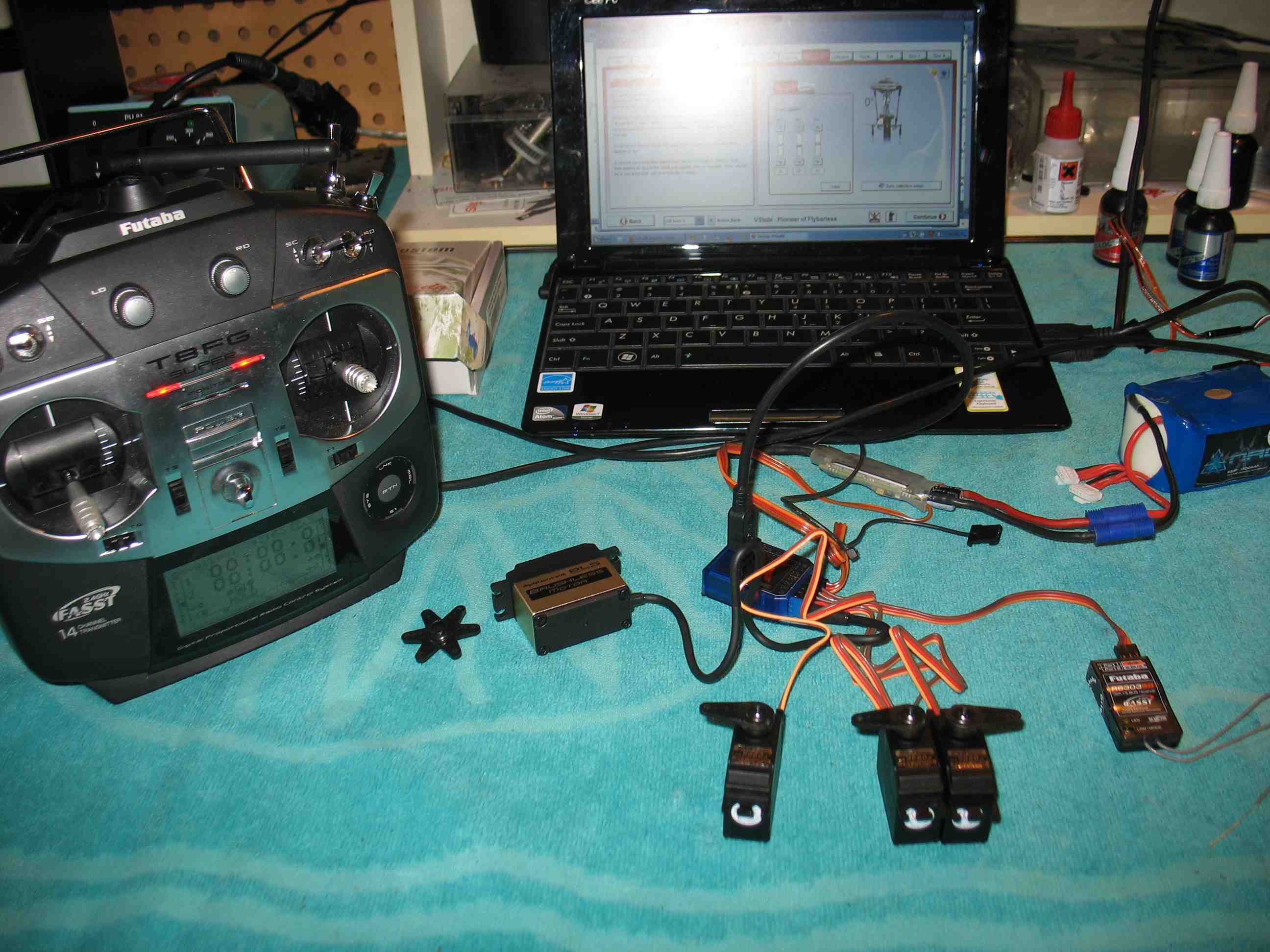 full resolution pic: http://rzavelli.home.xs4all.nl/stuff...s/IMG_2090.JPG Now we finally get to the fun part, actual wrenching! It's always a wise idea to degrease any critical metal threaded part of course (including bolts), prior thread locking. The servo horn ball studs in particular, since they are packed with the main shaft bearing. I usually use brake cleaner for degreasing. Main shaft blocks with servos attached. Screws aren't tightened yet, which obviously allows me to properly align the blocks with the frame plates and main shaft later. 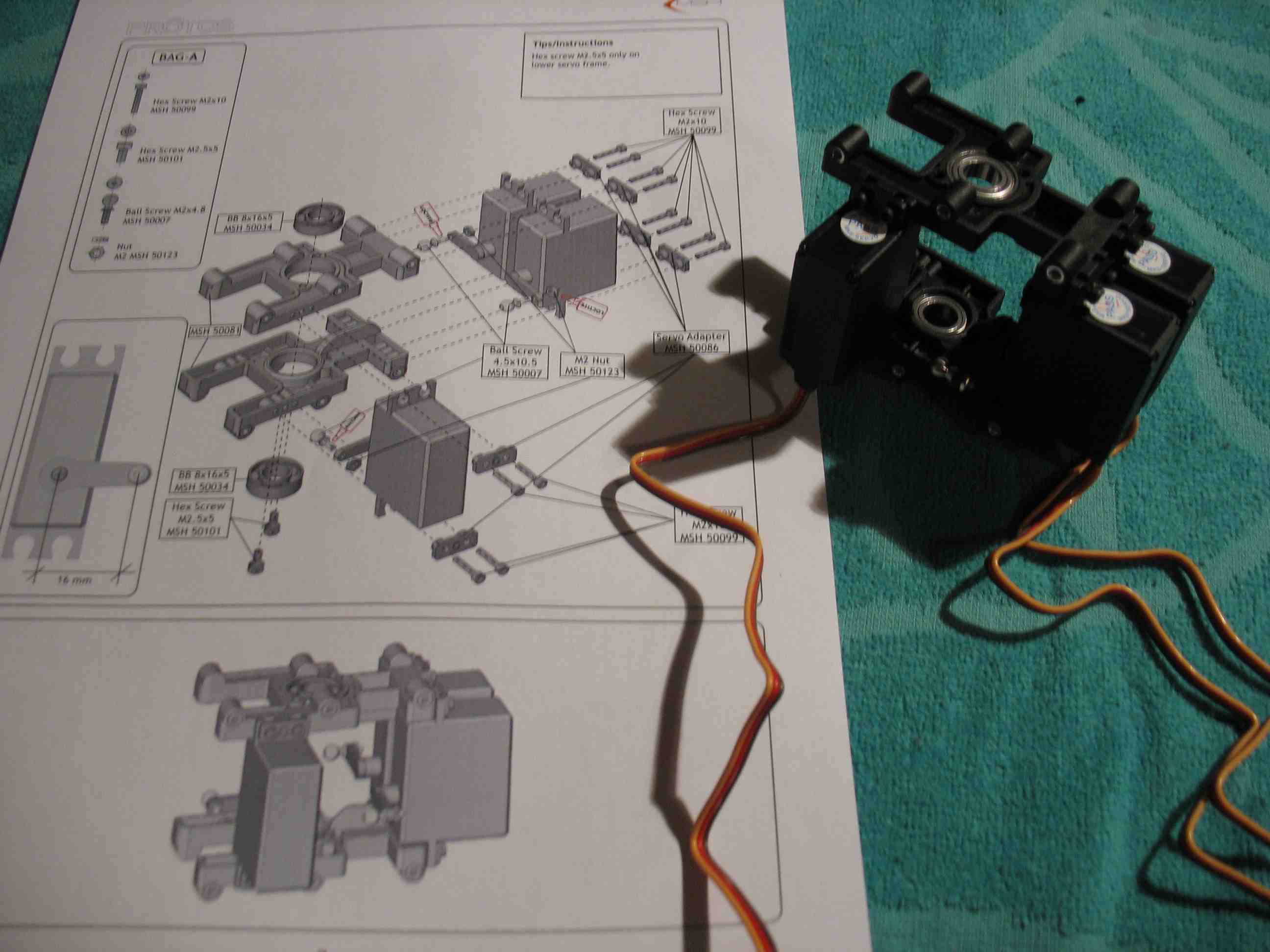 full resolution pic: http://rzavelli.home.xs4all.nl/stuff...s/IMG_2097.JPG It wouldn't be Italian if it didn't have some tolerance issues . CF frame thickness may be a bit on the upper tolerance end, since I had trouble inserting it in the moulded bottom plate without actually bending the frame plate. It was a tight fit with the Mini Protos, but for the Protos here it doesn't fit for me. Before pic: 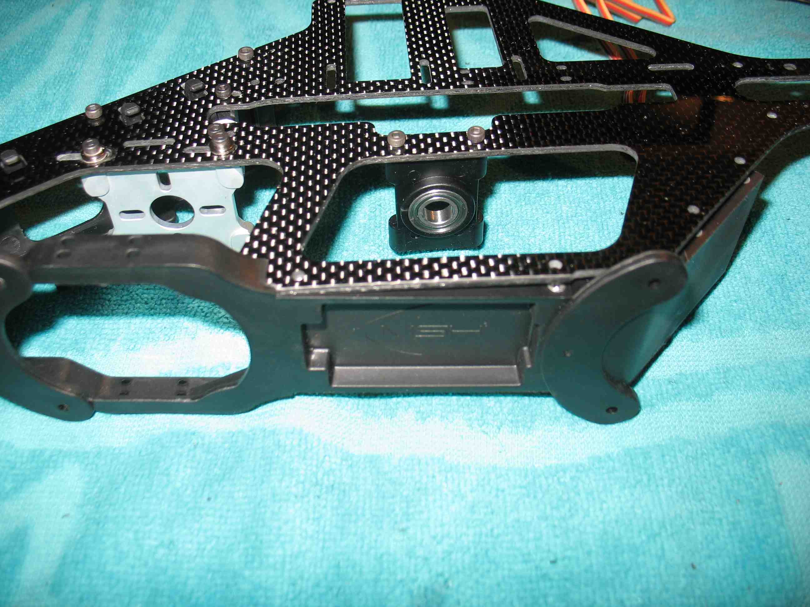 full resolution pic: http://rzavelli.home.xs4all.nl/stuff...s/IMG_2112.JPG I've used a small file to remove material on the inside of the arch on the moulded bottom plate, which relieved most of the stress. Half a frame assy, did not use thread lock here yet. Screws are still mostly loose, since I haven't inserted the main shaft yet: 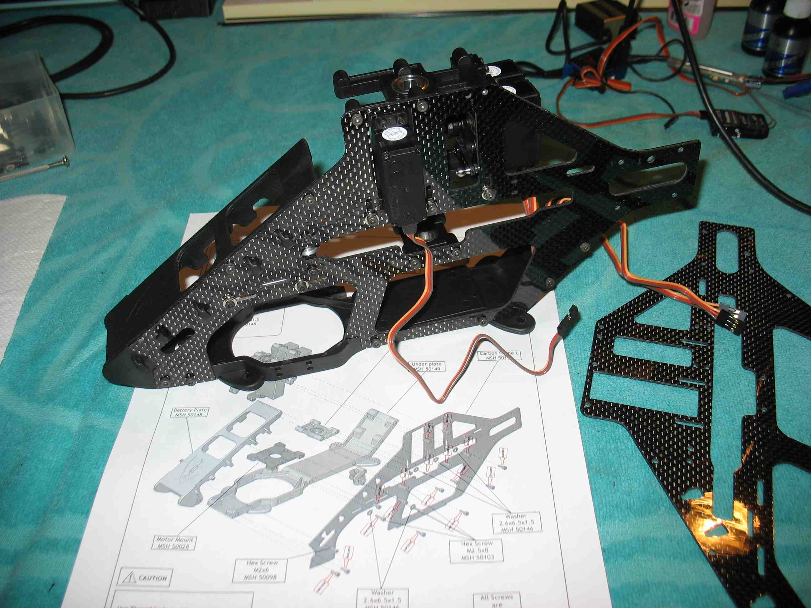 full resolution pic: http://rzavelli.home.xs4all.nl/stuff...s/IMG_2115.JPG 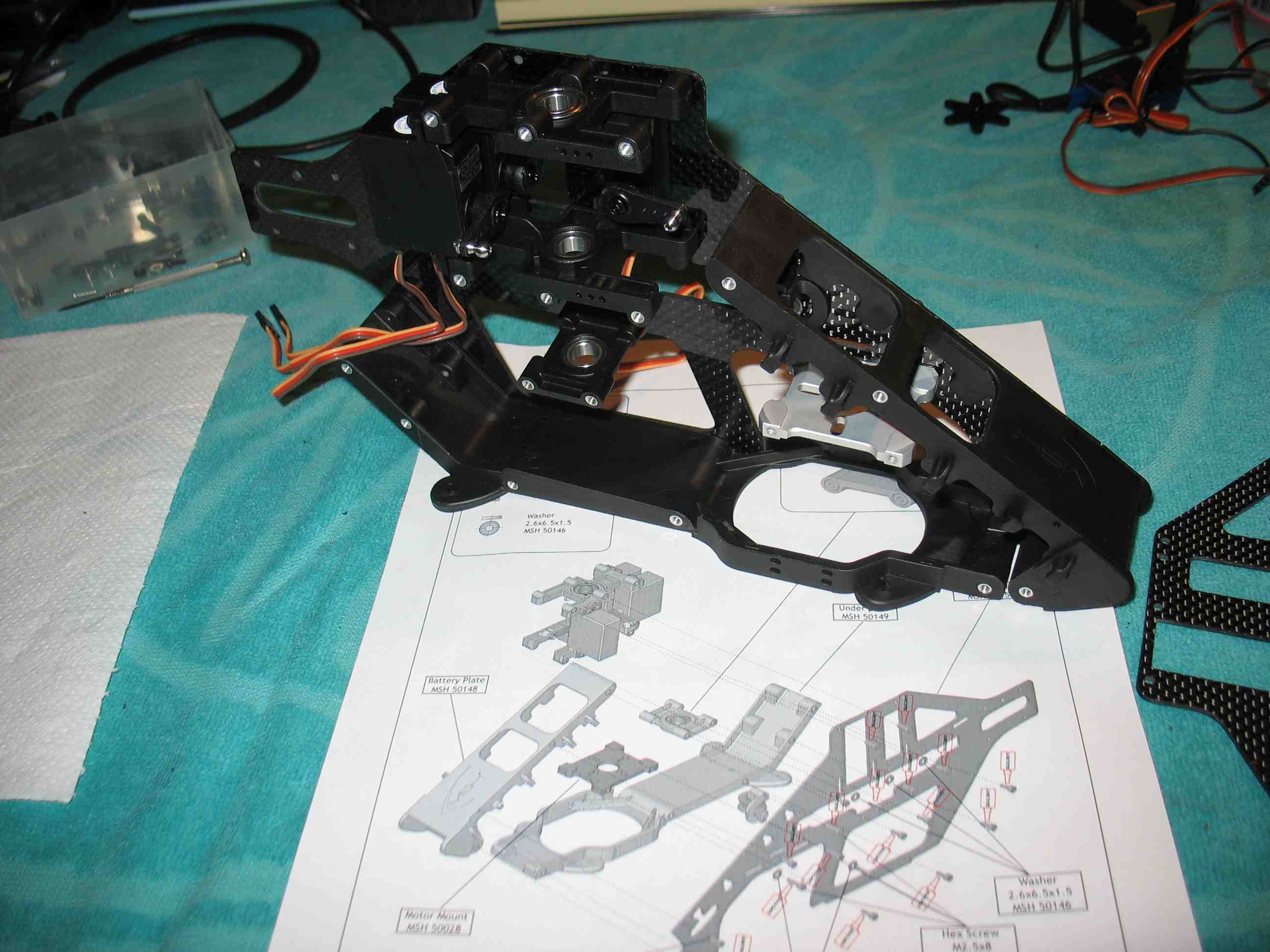 full resolution pic: http://rzavelli.home.xs4all.nl/stuff...s/IMG_2120.JPG Now, the newer Mini Protos has a slot in the frame to run the front swash servo wire cleanly down the inside of the frame. The Protos does not. At this point I'm considering removing the frame plate and milling a small slot in the Protos frame plate. 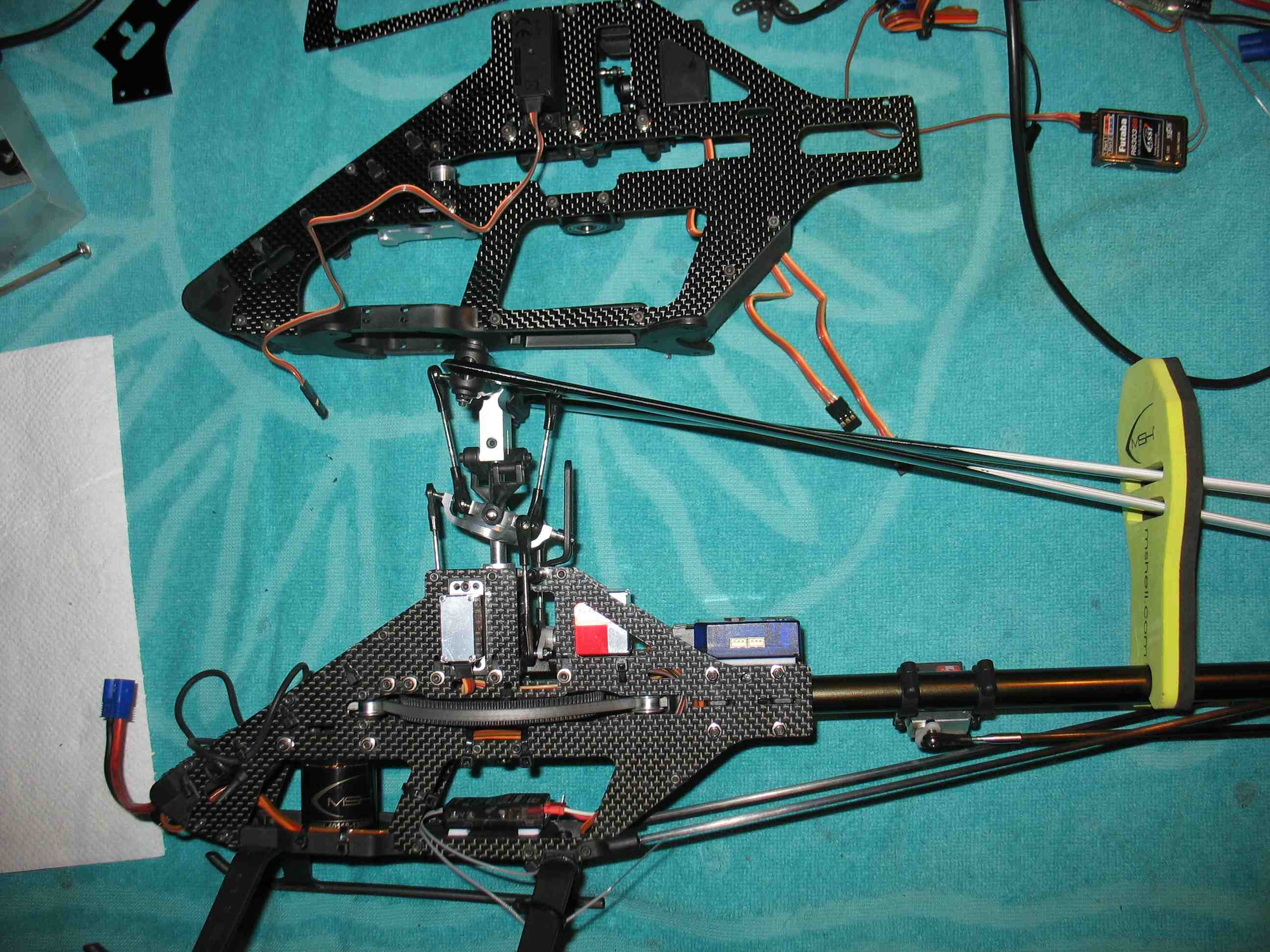 full resolution pic: http://rzavelli.home.xs4all.nl/stuff...s/IMG_2130.JPG To run the front swash wire down the inside of the frame, I opted to file a slot from the side, rather than making a rectangular slot. So, took the plate off, used a wet file and made a slot large enough for the connector to slide through. Then I blended the edges around the slot on both sides of the plate, to prevent wire chafing. 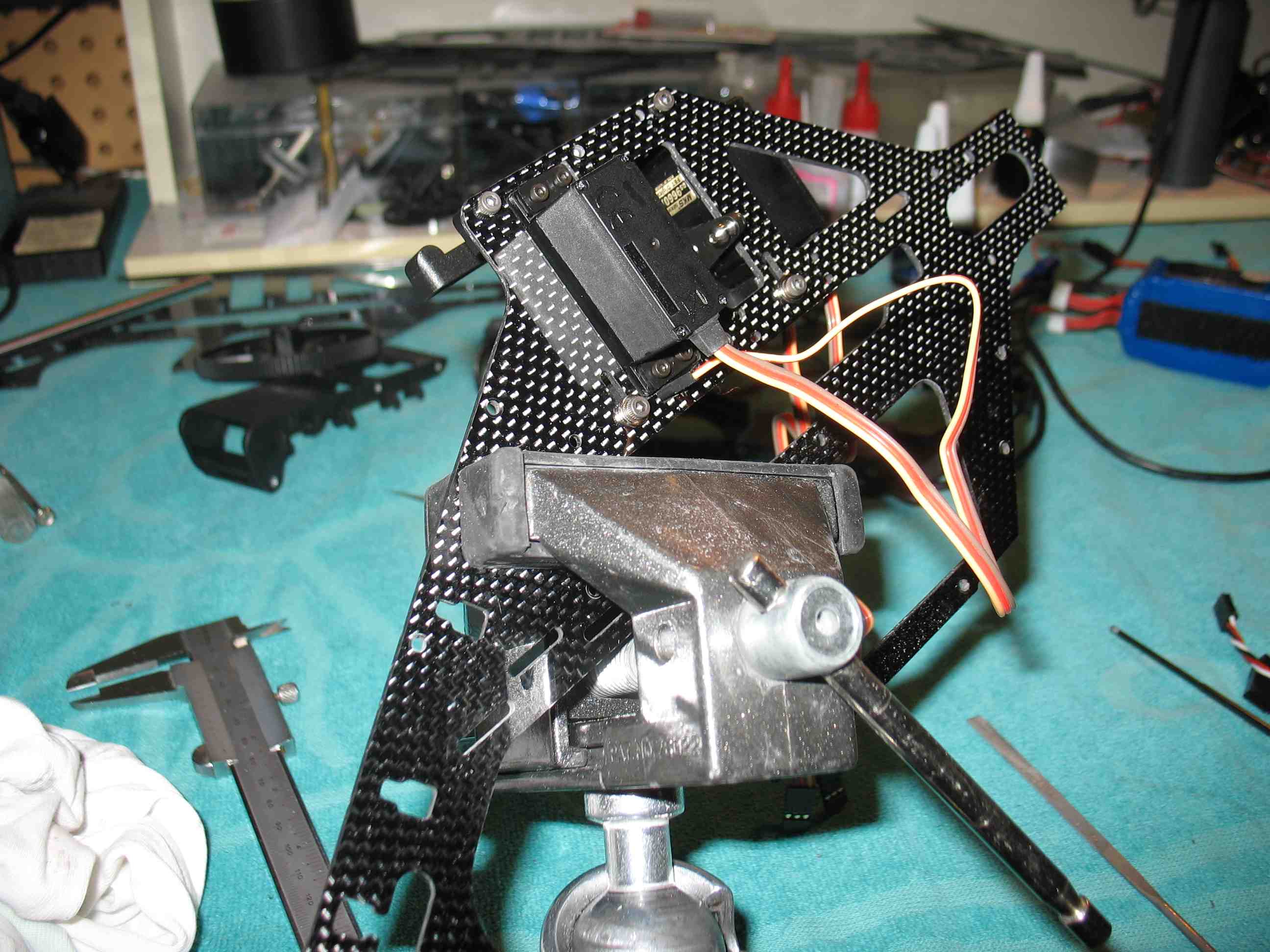 full resolution pic: http://rzavelli.home.xs4all.nl/stuff...s/IMG_2135.JPG Filed the arches on the inside of the moulded bottom plate some more, since the fit wasn't ok yet: 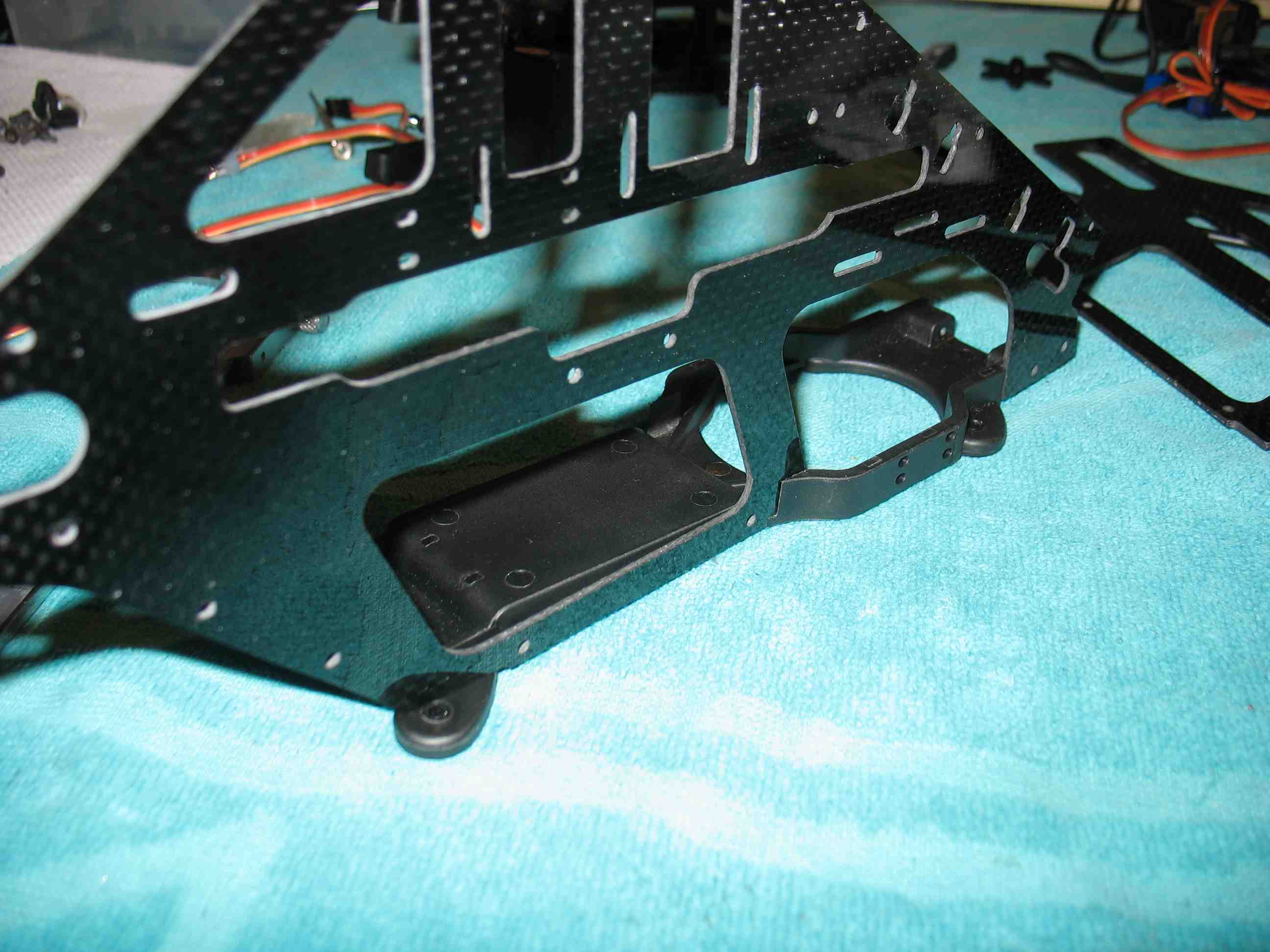 full resolution pic: http://rzavelli.home.xs4all.nl/stuff...s/IMG_2145.JPG Slightly over constrained still, but it will have to do: 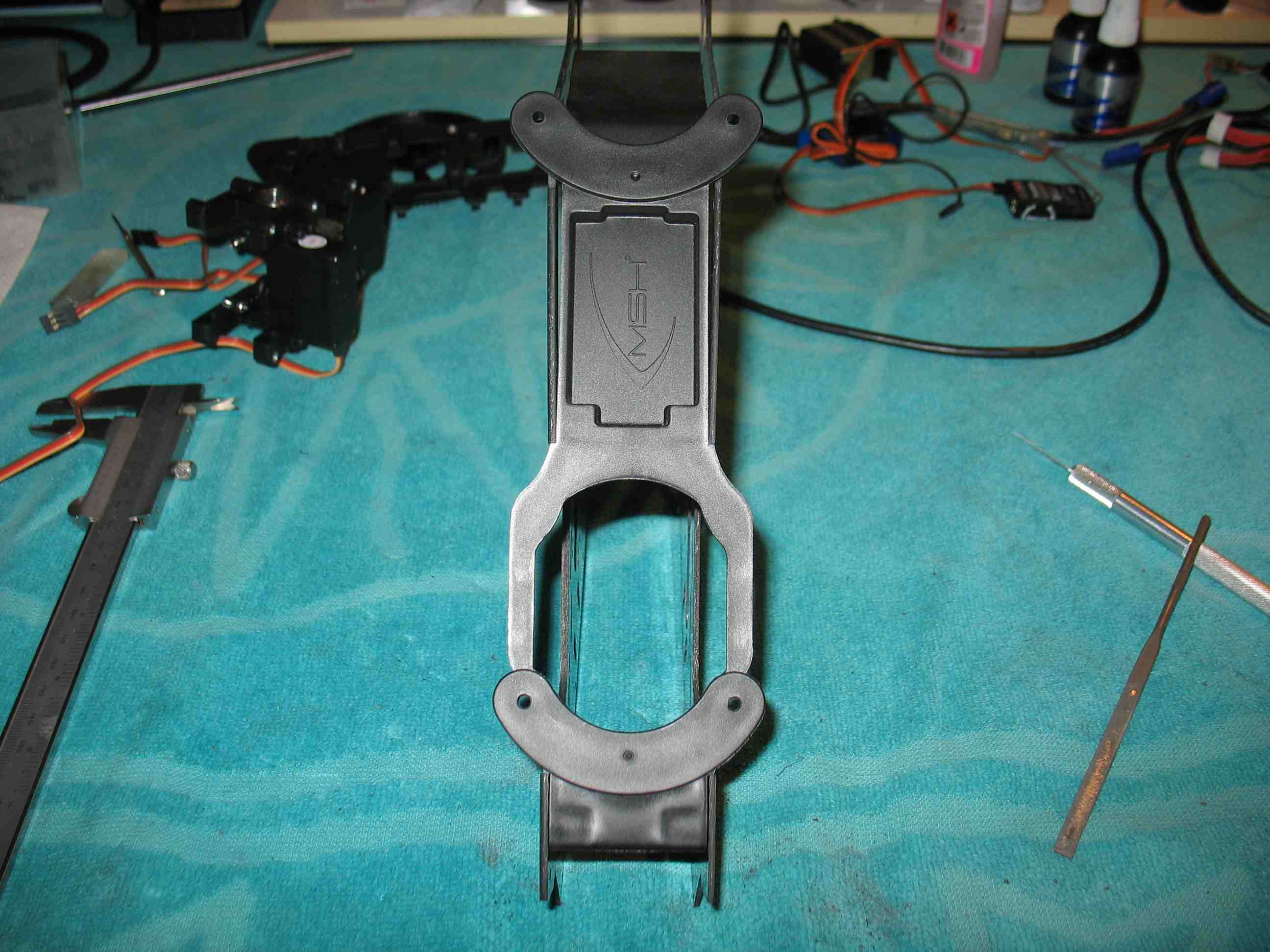 full resolution pic: http://rzavelli.home.xs4all.nl/stuff...s/IMG_2150.JPG Please don't look too long at the CF plate quality and thickness difference between the left and right plates, a big no-no for RC car racers, but it will have to do here: 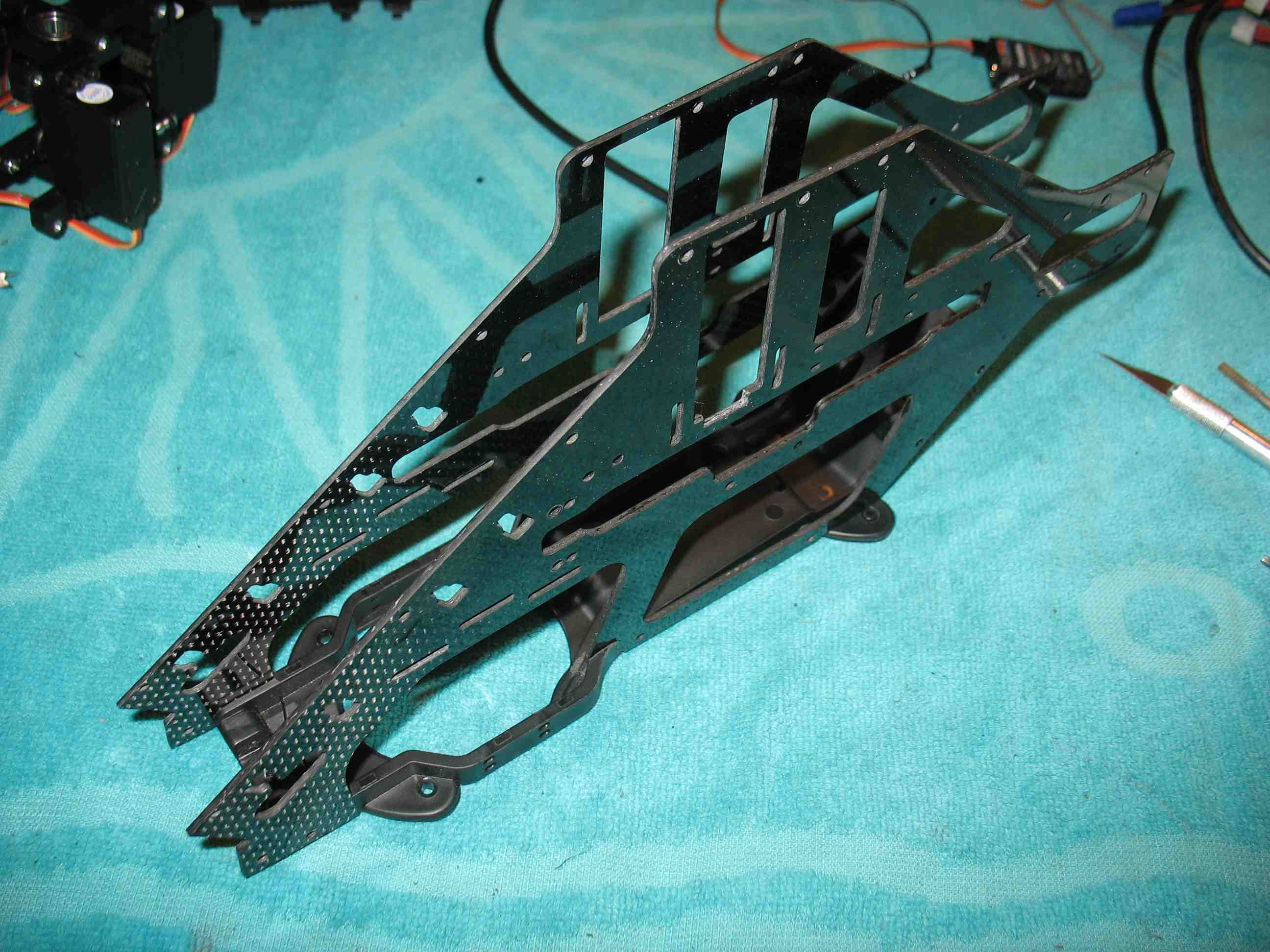 full resolution pic: http://rzavelli.home.xs4all.nl/stuff...s/IMG_2157.JPG My small mod allowing the front swash servo wire to run to the back down the inside of the frame: 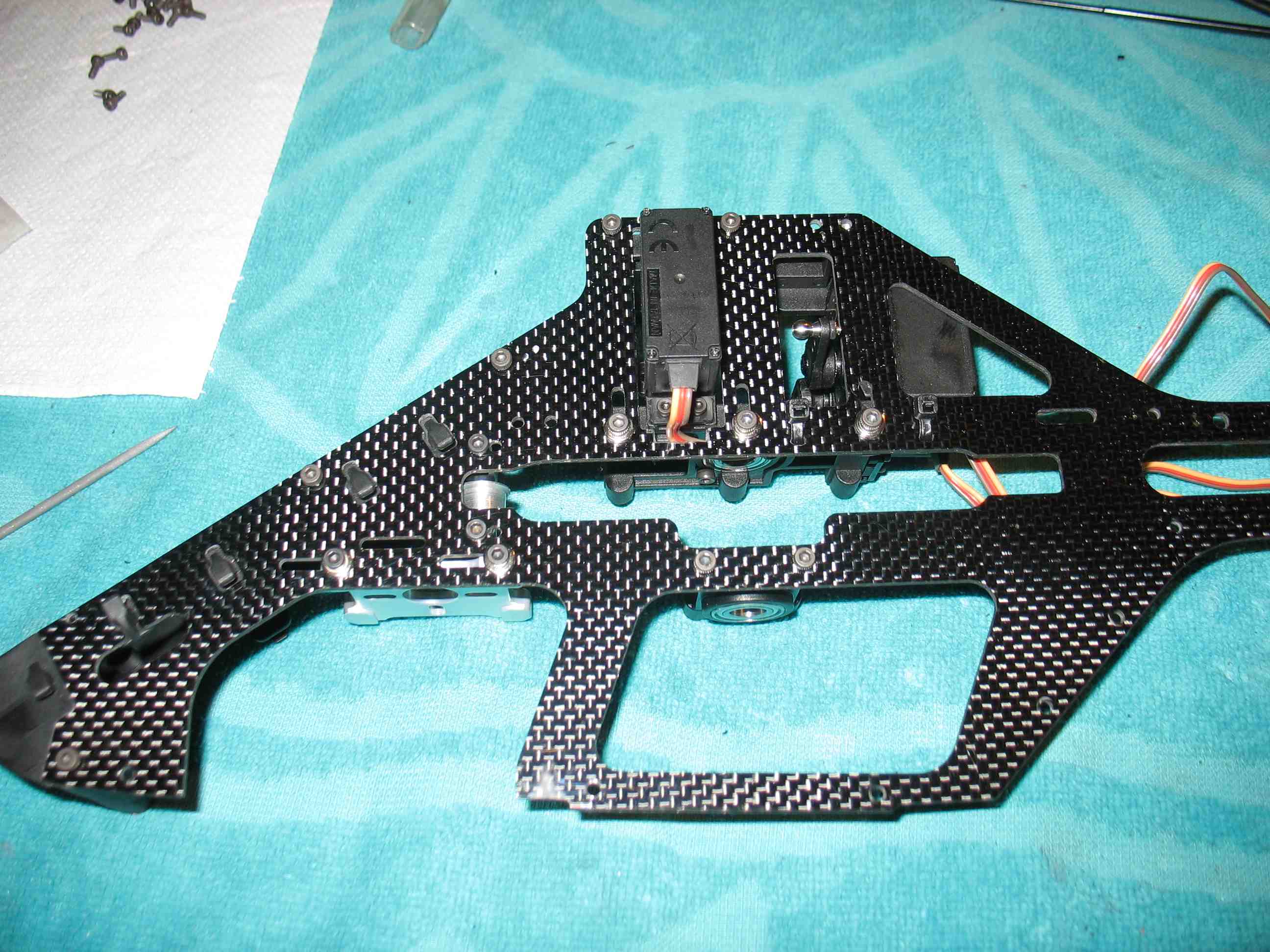 full resolution pic: http://rzavelli.home.xs4all.nl/stuff...s/IMG_2158.JPG On the inside, it looks like this: 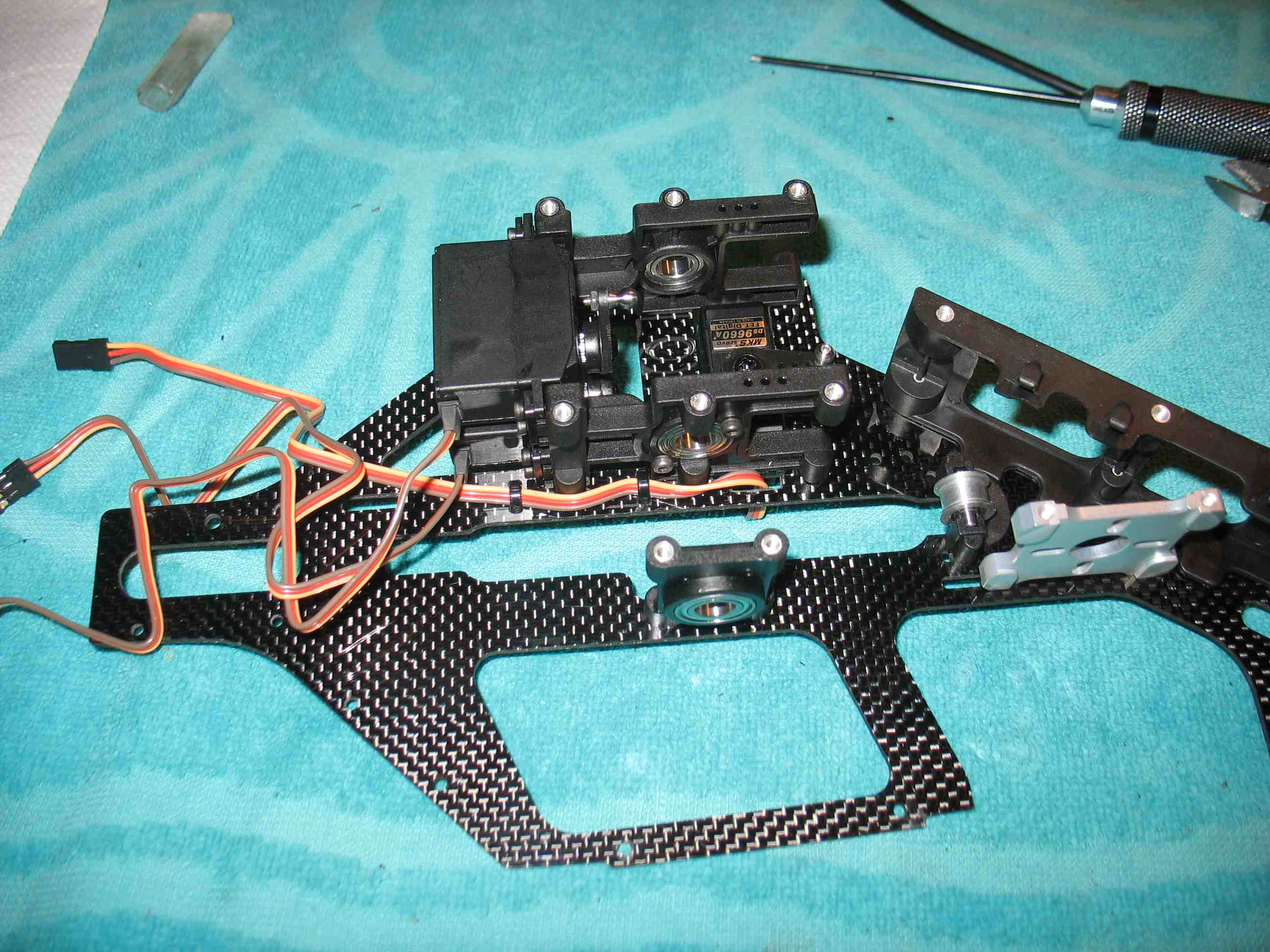 full resolution pic: http://rzavelli.home.xs4all.nl/stuff...s/IMG_2163.JPG Assembled the frames loosely, inserted the mainshaft, slowly cross tightening all bolts going round a few times, only to notice the coaxial alignment of the three main shaft bearings was way off. Most likely due to tolerance stackup. At first I experimented with shims a bit, then took the bottom bearing block out and filed down one of its sides until the three bearings were coaxially aligned with tightened frame bolts. It isn't that bad if the alignment isn't 100%, i.e. the shaft not falling down from its own weight. The side effect of that scenario, is that it stops the main shaft from spinning inside the ball bearing's inner rings. Anyway, this is how I ended up (after a lot of work): Applied thread lock to the frame bolts, one by one, leaving the frame assembled. Afterwards I fixated the twelve servo bolts. I didn't thread lock the bottom plate bolts yet, since for installing the motor and ESC, it's easier to have that part removed. At this point the manual directs you to install the landing gear, which I won't do yet, since I find it easier to wrench on the thing without. 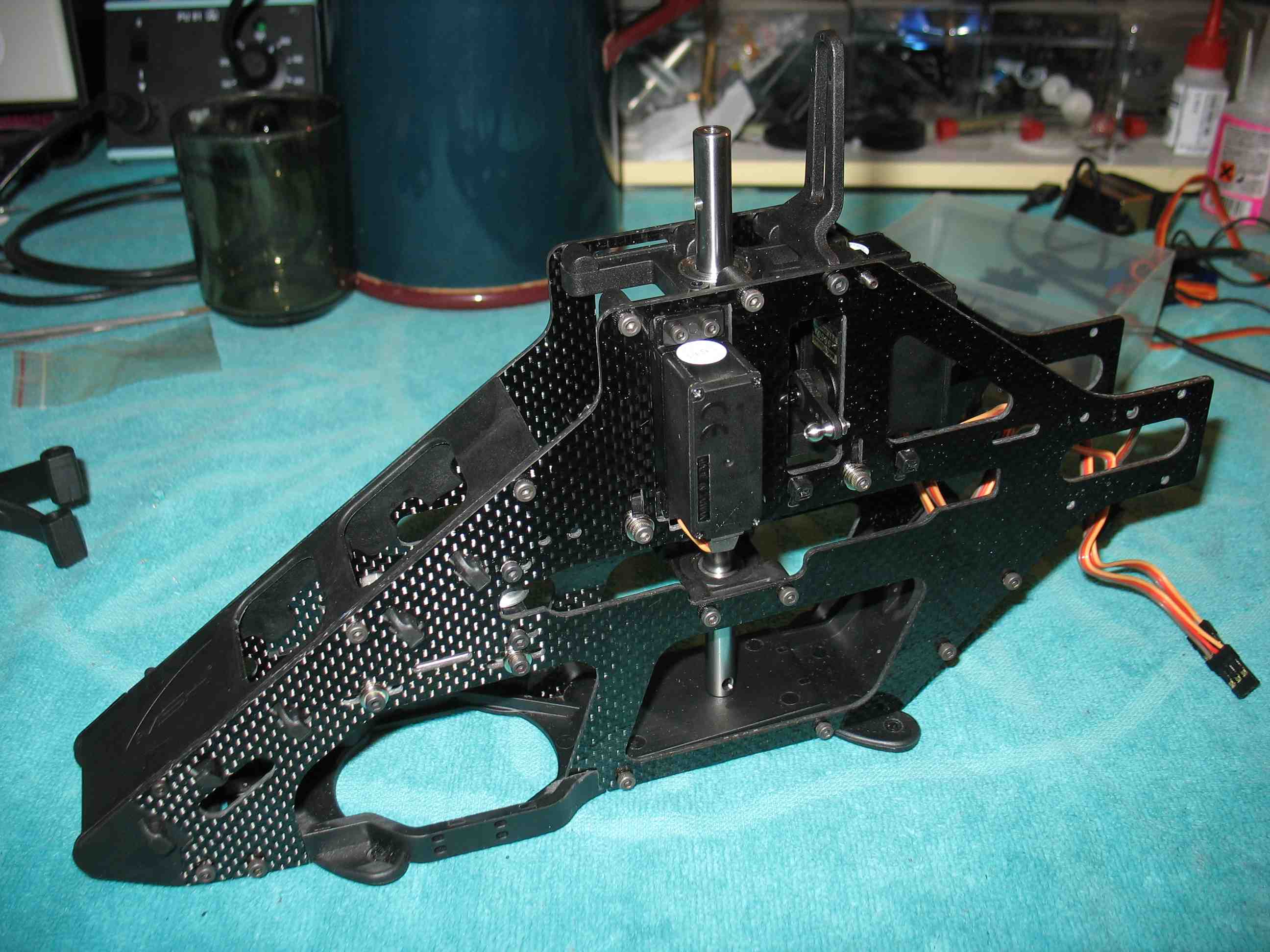 full resolution pic: http://rzavelli.home.xs4all.nl/stuff...s/IMG_2171.JPG The canopy mount M2.5x12 metric set screws come with a 1.3mm hex, as per the norm. A .050" (1.27mm) imperial hex screw driver fits perfectly here. When bottomed out, the screws weren't sticking out far enough for my taste, so I unscrewed them, leaving 4mm sticking out, then left the thread lock to cure overnight. Then screwed the canopy posts on today. Sprayed the belt with silicone spray before heading to the office yesterday morning, only to find it still wet this morning. Oops, overdid it a bit. Wiped it a bit. (On my Mini Protos, I tend to spray a belt once before installing it, then leave it like that until it is replaced.) Installed the belt, main shaft and main pulley. Ok, now the most confusing bit of this helicopter. It is delivered as a flybarred machine. However, there are not one, but two FBL upgrades. 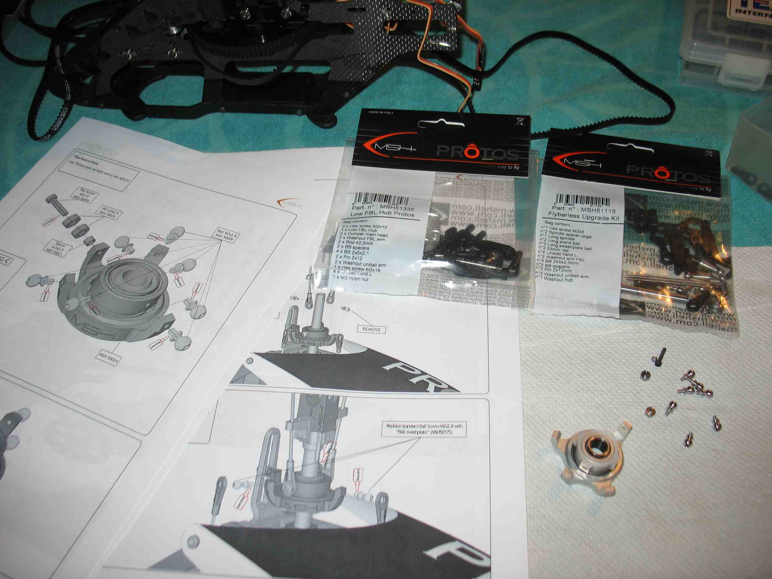 full resolution pic: http://rzavelli.home.xs4all.nl/stuff...s/IMG_2185.JPG You need the long ball studs from the first upgrade on the swash. I degreased all ball studs and the thread holes with brake cleaner prior thread locking them. MSH51115 Flybarless upgrade Kit Comes with long ball studs for the swash, long ball studs for the main blade grips and a different length feathering shaft. Also has pitch links, swash drivers and a swash driver mount which is used with the conventional flybarred hub (the one with the hole in it). There used to be a manual for this upgrade available for download on the MSHeli site, it isn't anymore. I still have it in my RC heli archive from downloading it a year ago, however its contents do not match the contents in the bag. Uhuh. MSH51335 Low flybarless hub (only stretched protos) The second upgrade, contains a low FBL hub, shorter pitch links and swash drivers which are mounted directly onto the hub. You need some of the parts from the first upgrade, to be able to use this upgrade. The reason why the low hub may only be used on a stretched Protos, is because when used on a non-stretched kit, your main blades supposedly may start a war with your tail blades. In other words, the boom wouldn't be long enough. So basically, I'm looking at a flybarred Protos manual, a non up to date FBL appendix, parts from the kit and two upgrade bags, to build a low FBL head. Also, at times, one is looking at the manual for the stretch kit conversion. Uhuh. I hate assembling pitch links. This is the method I use for the servo to swash links, no link pliers involved: Rods are 42.5mm According the manual, base reference distance required between the plastic joints is 28mm Joints have to be screwed on 7.25mm per side (42.5-28)/2=7.25 I clamp a rod in the vice Roughly screw just one joint on by hand Target a 35.25 remaining length of the rod 42.5-7.25=35.25 Clamp the rod with the other end facing up and screw on the remaining joint Measure the in between length, fine adjust to 28mm You can also eyeball it, I prefer the above. Swash installed: 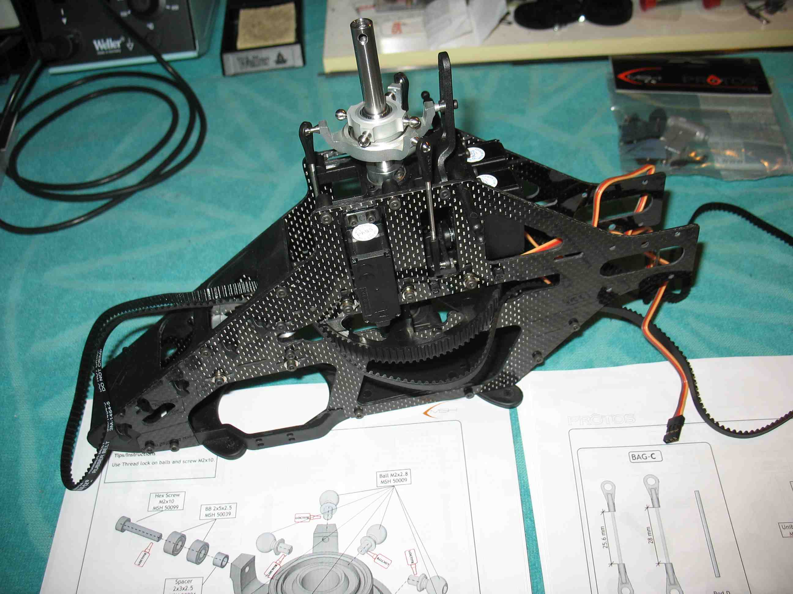 full resolution pic: http://rzavelli.home.xs4all.nl/stuff...s/IMG_2199.JPG Now we can go and level the swash. I prefer the redneck method with a tiewrap. The benefit of this is that it's also possible to level the swash with a fully assembled head. 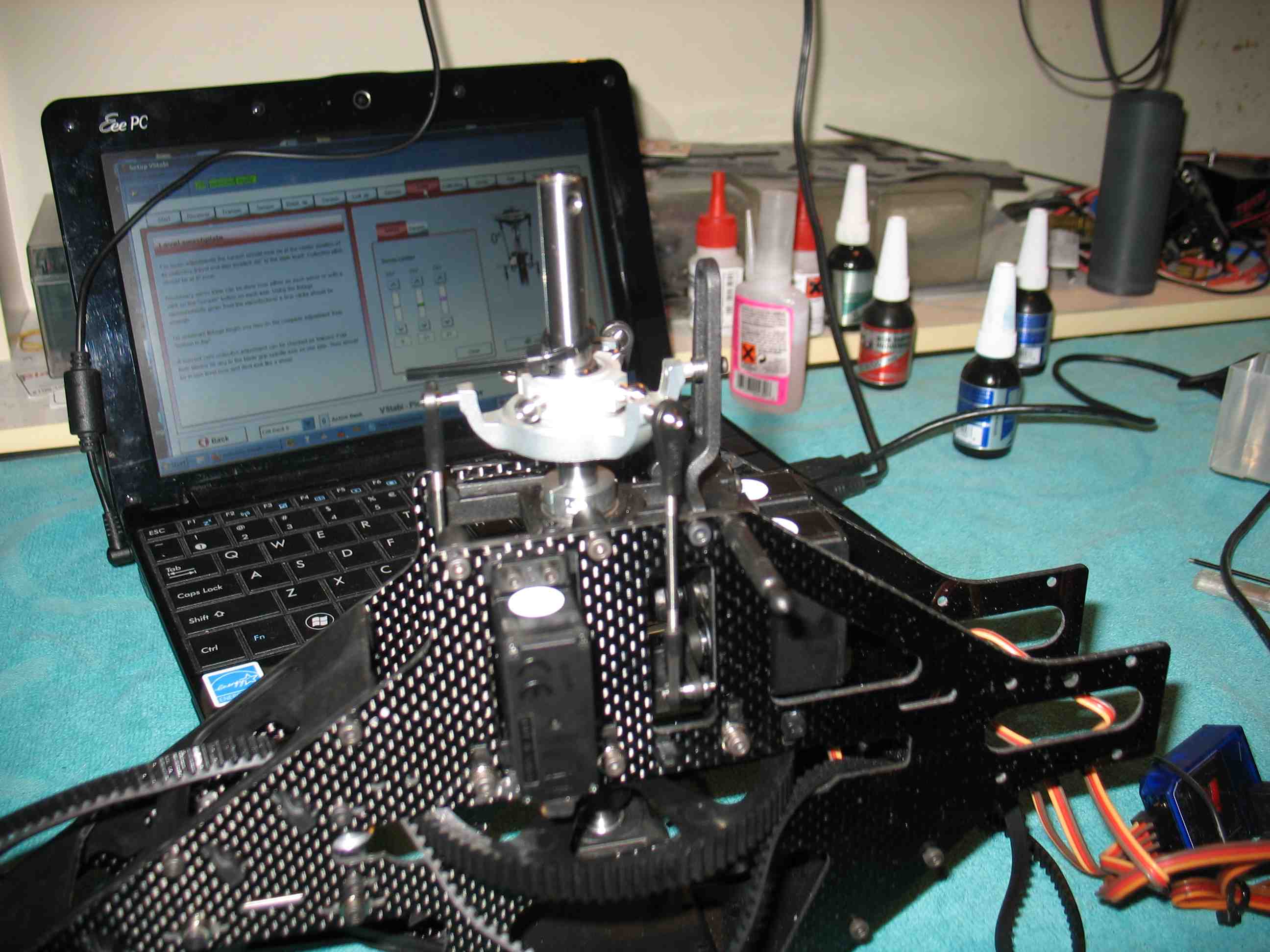 full resolution pic: http://rzavelli.home.xs4all.nl/stuff...s/IMG_2207.JPG I numbered the servos with a marker earlier, which comes to good use now when trimming in the V-Bar software. I'm just looking for an equally spaced gap between the tie wrap and the plastic joints on all three points. Provided the servo horns were properly perpendicular aligned earlier and everything was built right, one barely has to adjust anything here. I needed just two clicks on one of the servos to level the swash. The pro version of the V-Bar software allows you to level the swash as well at full negative and positive pitch positions, eliminating any possible interaction caused by different servo orientations, servo horn ball stud axial and radial variations. Full negative pitch, only had to adjust one click: 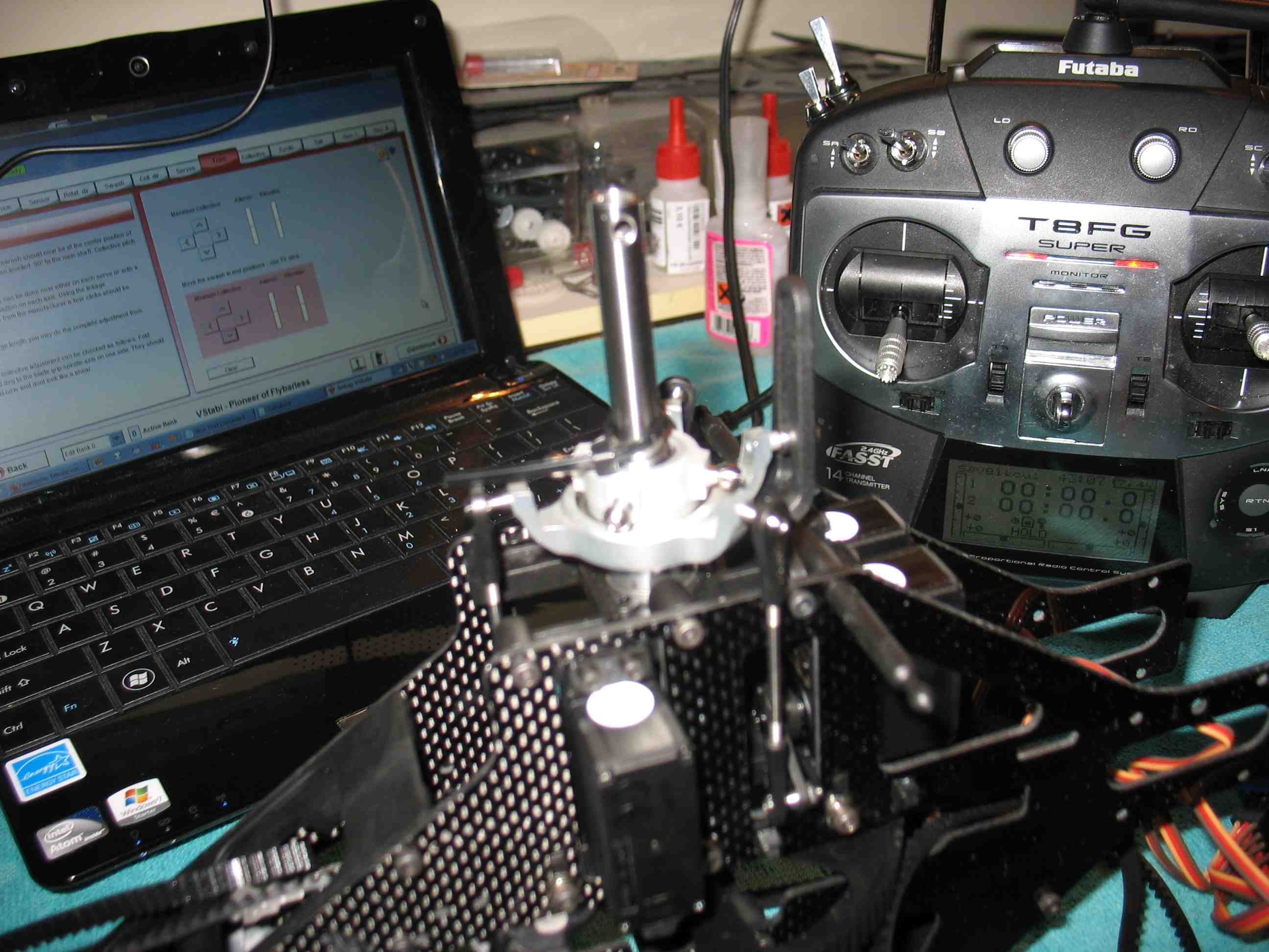 full resolution pic: http://rzavelli.home.xs4all.nl/stuff...s/IMG_2215.JPG Full positive pitch, only had to adjust one click here as well: 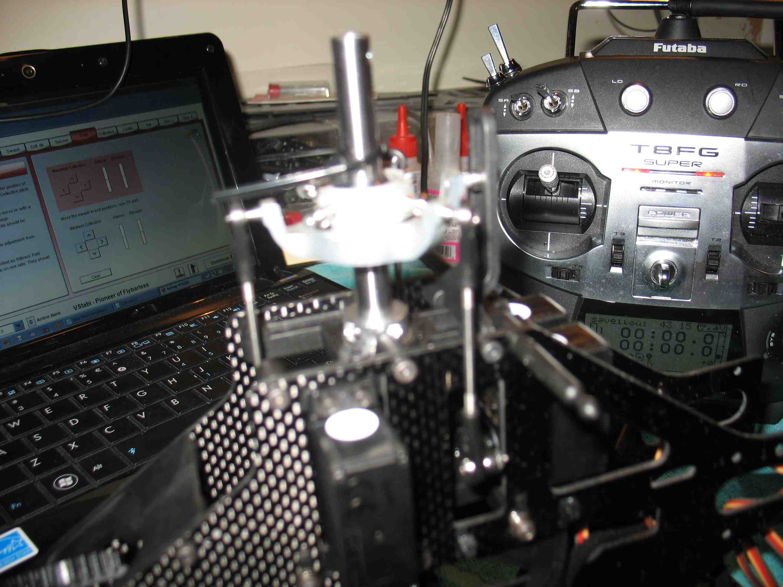 full resolution pic: http://rzavelli.home.xs4all.nl/stuff...s/IMG_2217.JPG There are full negative/positive and cyclic stick combinations possible where the links ever so slightly touch the frame. I could prevent this using cyclic ring in the V-Bar software, but I'm gonna be lazy for now and assume my collective management skills are good enough to prevent this from happening in flight at this point. Can always readjust this later . I'm gonna spare you all with pics of the assembling of the head, finding the required parts with the absence of up to date documentation was challenging, to say the least. The feathering shaft setup is fairly conventional, typical radial and thrust bearings positioning. Also, the shim to pass the axial forces down the inner ring of the outer ball bearing. I used some Associated silicone diff grease on the dampeners. I've ran the Mini Protos with and without grease, didn't notice a difference in flying or wear. Used Associated black grease on the thrust bearings. Unfortunately there are no shims included in this design to set dampening preload, something often used to compensate for tolerance stackup variations. The dampening feels pretty nice and tight as it is now, a number of flights will point out whether it suffices. It's important not to forget installing the tiny spacers in between the bearings of the swash driver arms, since they transfer the clamping force of the bolt through the inner ball bearing rings. Failing to include these will bind the bearings, when tightening the bolts onto the hub. I'll give you a pic of the assembled head and all the unused parts at this point of the build. Yep, I paid for all of those parts in the tray and the bag, unlikely to use them. 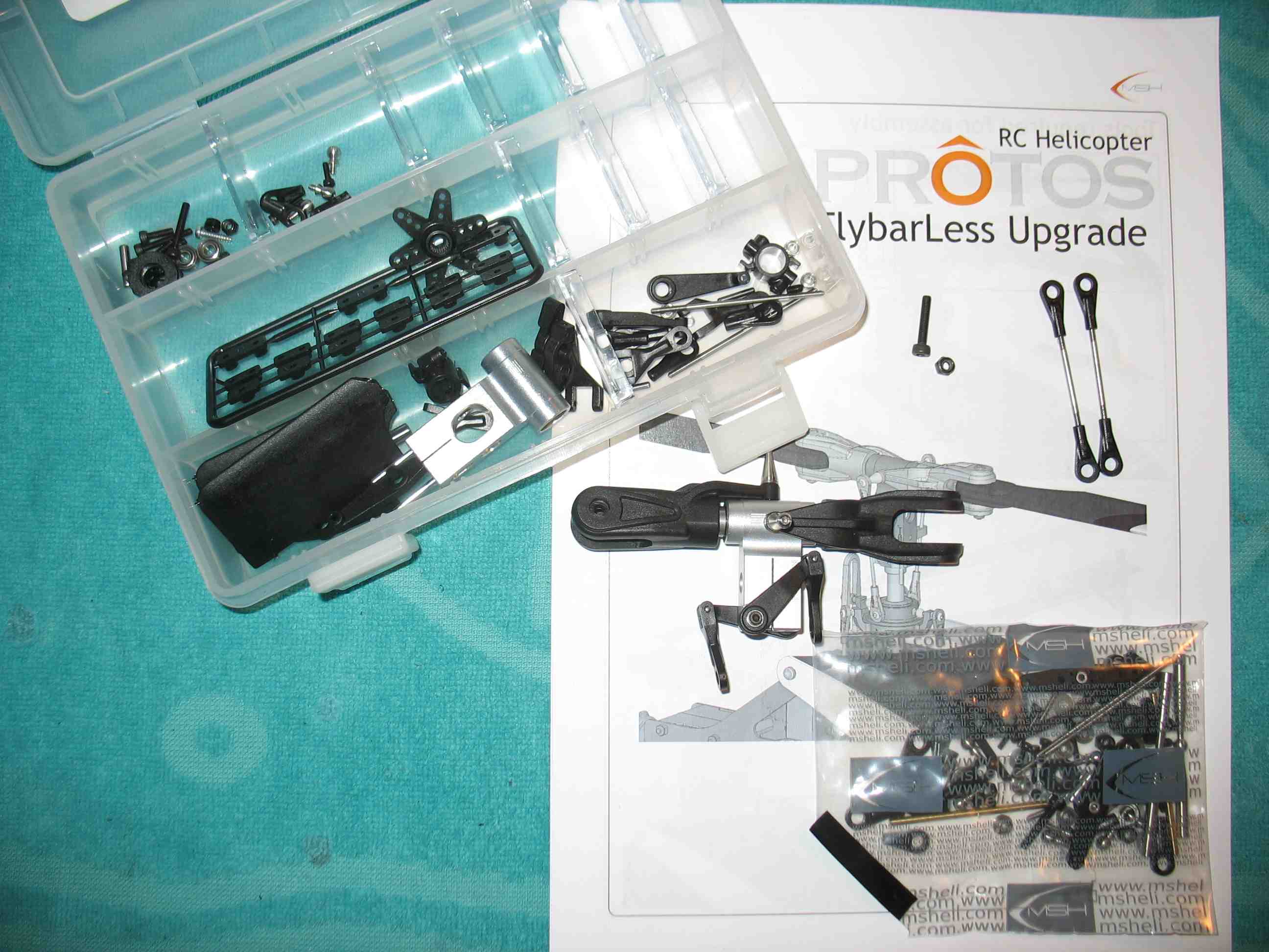 full resolution pic: http://rzavelli.home.xs4all.nl/stuff...s/IMG_2218.JPG Due to absence of documentation, I started with 28mm distance between the pitch link joints. It turned out one of the blade grip ball studs was undersized, causing a lot of joint play. Fortunately I still had some Mini Protos spare ones laying around, which turned out to be the same ones. Now, it is time to go back to the swash trimming screen of the V-Bar software again. Not to trim anything, but just to get absolute midstick without the gyros being active. Time to set up 0° pitch and blade tracking. I like to set the frame parallel to the edge of the table, then eye-balling the feathering shaft perpendicular to the frame. Then I use a wrench which just about fits through the main blade holder. Then I sit down on the ground, using one eye to align the wrench with the hub Jesus bolt. Then I look down, near the main shaft collar, to see where the wrench is. It should be in the middle of the main shaft, naturally. This method works way better for me, than messing with a pitch gauge or folding blades together. Never ever have to redo blade tracking at the field with the wrench method. Note, the main shaft isn't perpendicular to the bottom of the frame. You have to look at the wrench in relation to the main shaft at the bottom and the Jezus bolt at the top. This was the initial angle, with guessed pitch link length: 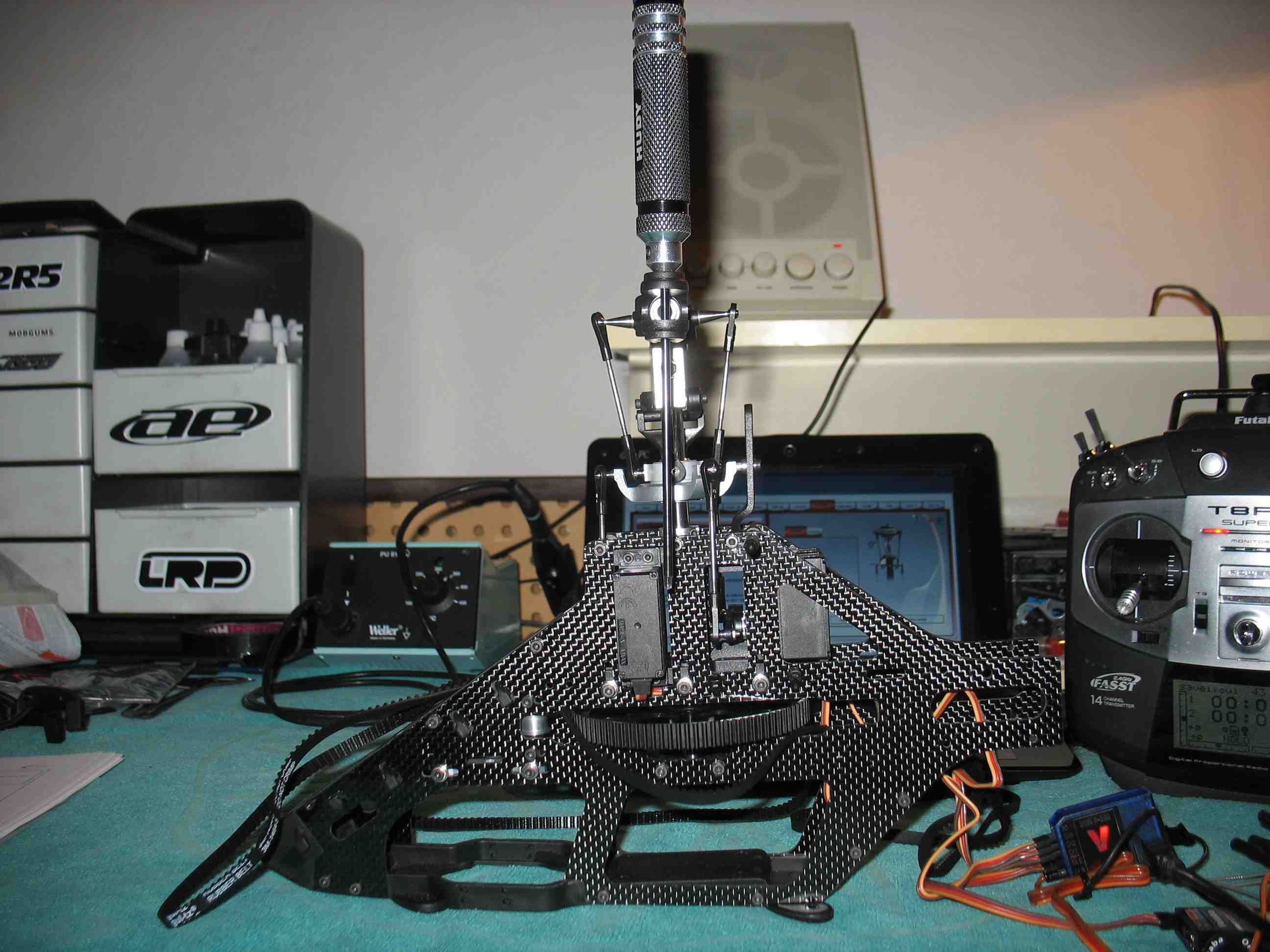 full resolution pic: http://rzavelli.home.xs4all.nl/stuff...s/IMG_2225.JPG After some adjusting, I ended up with this: 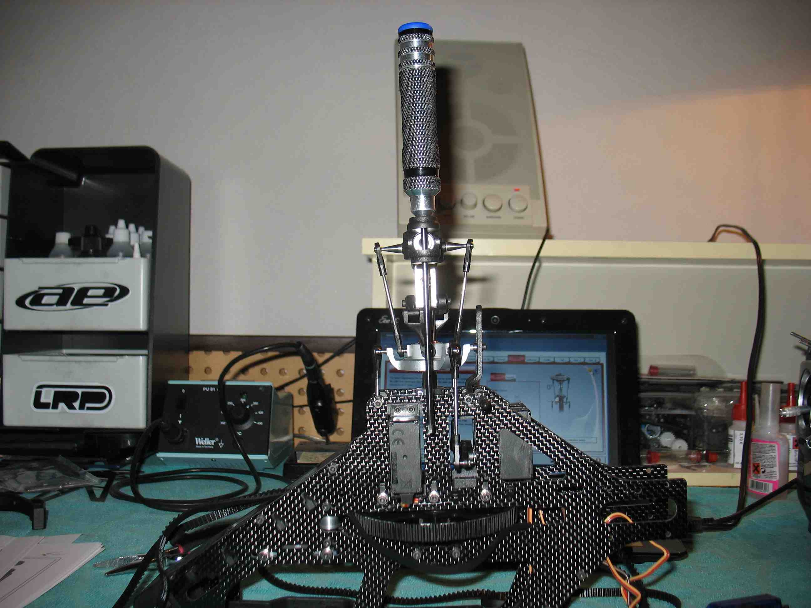 full resolution pic: http://rzavelli.home.xs4all.nl/stuff...s/IMG_2251.JPG The pitch link length ended up being about 26.75mm in between the joints. Tail time! First, servo horn aligning. Back to the V-Bar swash trim setup screen again to get a centered tail servo with disabled gyro. There's no way to trim the tail servo, other than mechanically, so it's important to pick a servo horn position that is reasonably perpendicular. Position 6 on this horn seemed to work best for me with this particular servo. 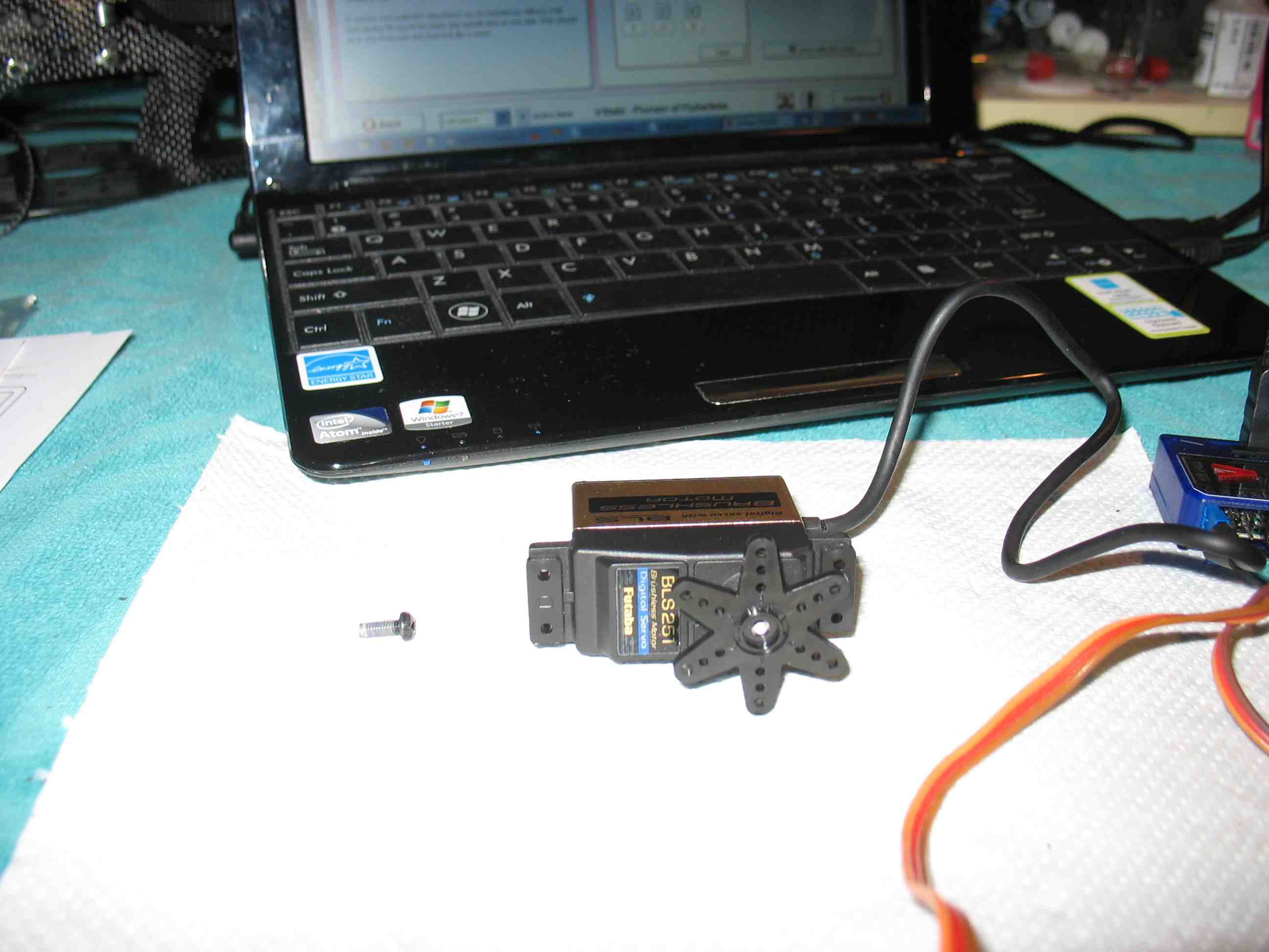 full resolution pic: http://rzavelli.home.xs4all.nl/stuff...s/IMG_2261.JPG Some more annoying servo horn trimming, of course it has to look neat: 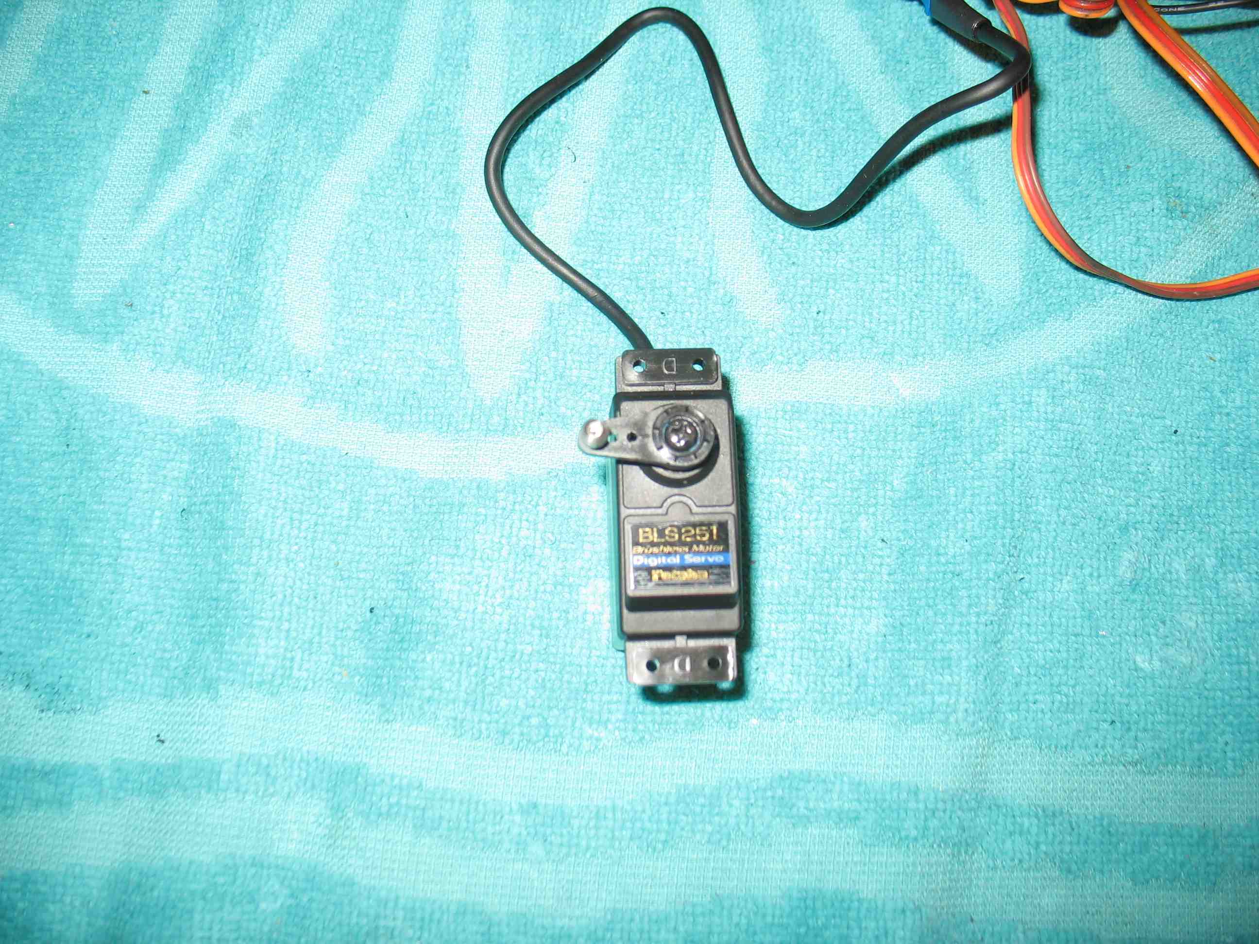 full resolution pic: http://rzavelli.home.xs4all.nl/stuff...s/IMG_2282.JPG The BLS251 servo wires have some thick mantle. I had to file some slots in the tail mount to be able to run it within the frames: 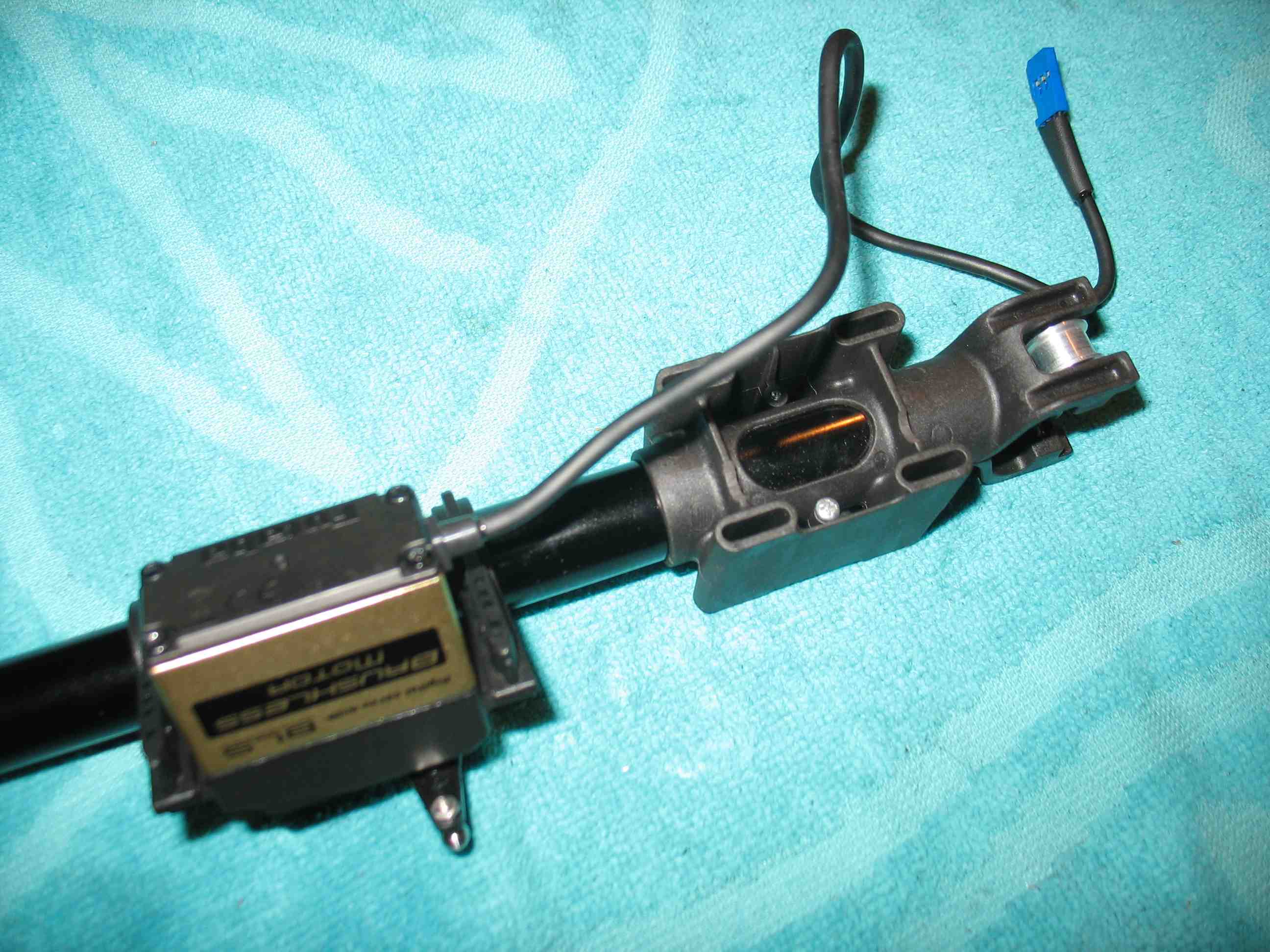 full resolution pic: http://rzavelli.home.xs4all.nl/stuff...s/IMG_2288.JPG One of the nice features of the Protos and Mini Protos is this bit. It is possible to leave all servo wires at their default length, yet run them inside the frames and hide them from sight completely. Behind the guide pulleys are two canals to stuff the servo wires down and back up. Very nice! 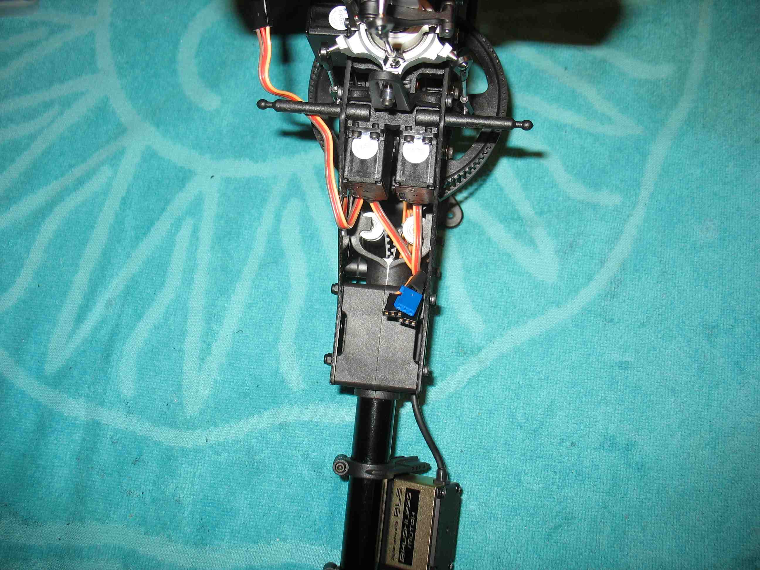 full resolution pic: http://rzavelli.home.xs4all.nl/stuff...s/IMG_2297.JPG Still have to tidy it up, but you get the idea: 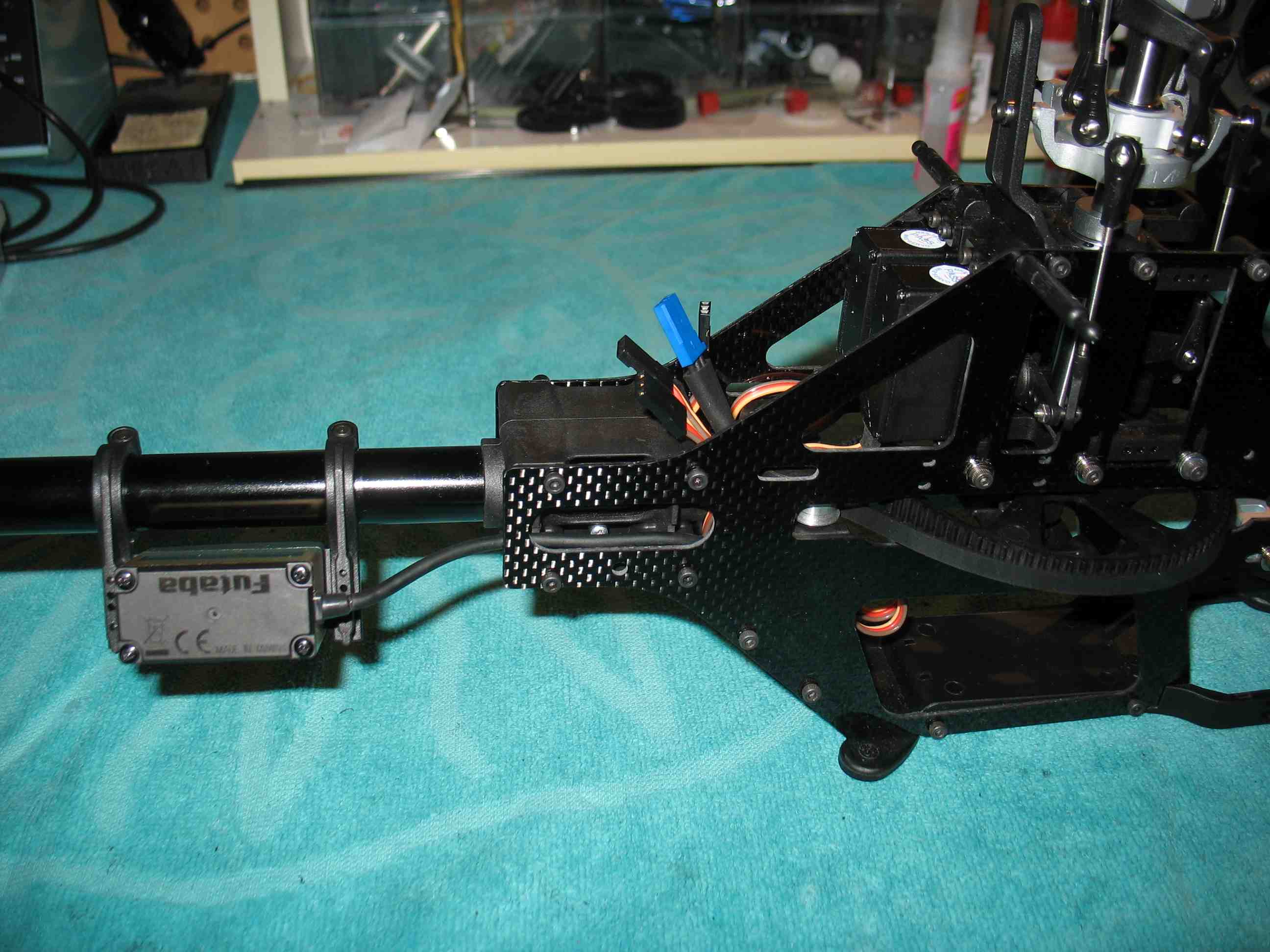 full resolution pic: http://rzavelli.home.xs4all.nl/stuff...s/IMG_2303.JPG Now, the tailshaft case assembly. By default you have to install two shims to eliminate axial play of the pulley in the tailcase. The kit includes two extra undocumented shims to eliminate further possible play. Any play here will directly affect tail authority, since the whole hub assembly will be able to move left and right. Note the Al. 18T stretched pulley here and the plastic non-stretched 20T stock one. 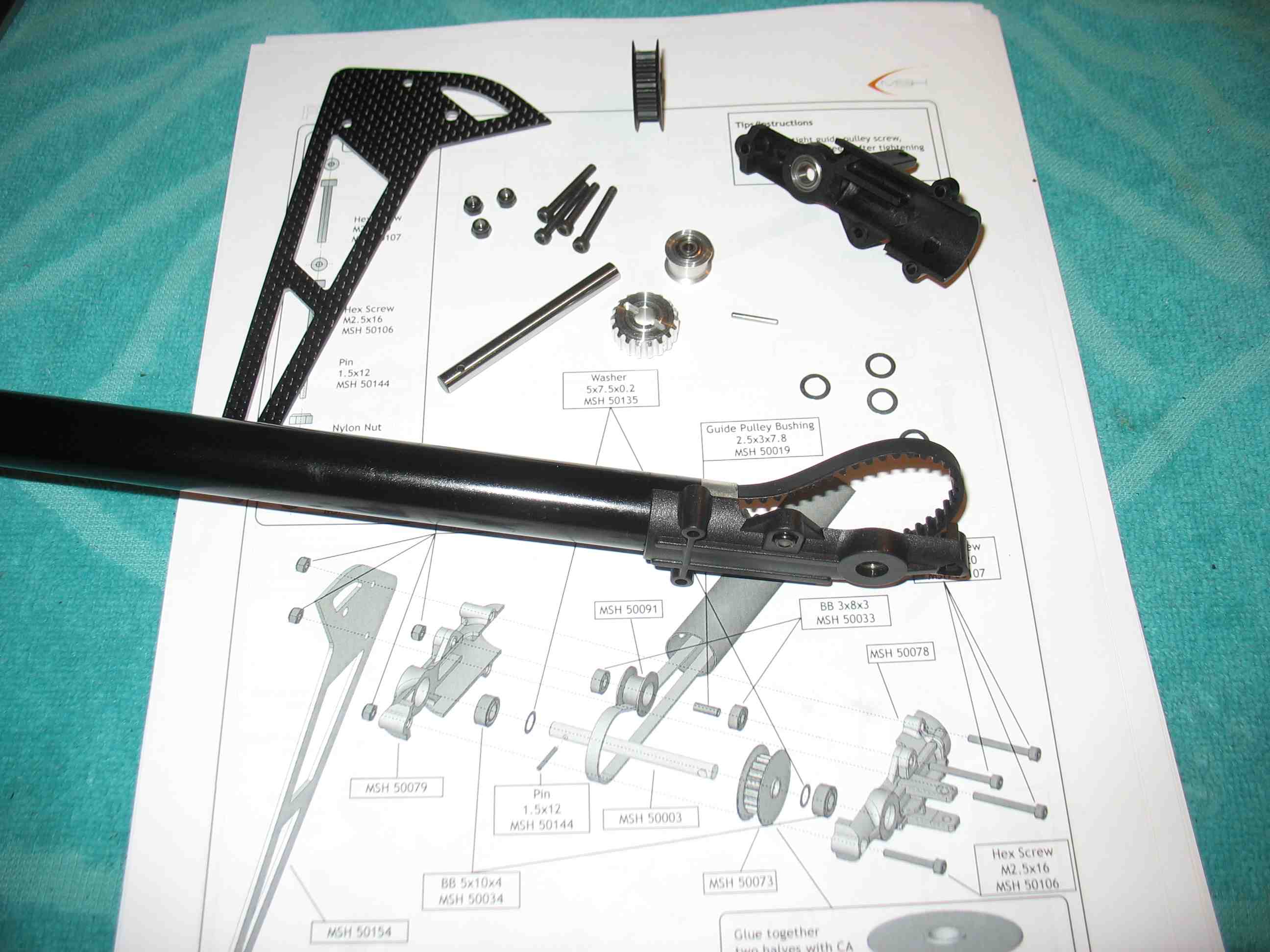 full resolution pic: http://rzavelli.home.xs4all.nl/stuff...s/IMG_2321.JPG With one shim either side, I ended up like this: However, it turned out, for me, the pin had too much play in the tail pulley, causing axial play of the complete shaft. Shims won't help you with that. Now I had two options: File down one side of the pulley, thus reducing the height of the pin slot, then adding extra shims in the assembly to compensate for the reduced pulley width. Use fitting green retaining compound to lock the pulley onto the shaft. Easy fix, but more work in the event of maintenance to get stuff apart. I chose the latter option, using just one shim on either side of the tail pulley. It turned out to be perfect. No feel-able axial play, but free spinning. Be careful with tightening the rear bolt of the tail case, it has a profound effect on tail shaft axial play. Boom support ends epoxy gluing, I sand the ends to remove the coating and to rough them up, using a bit of tape to prevent sanding further than needed. 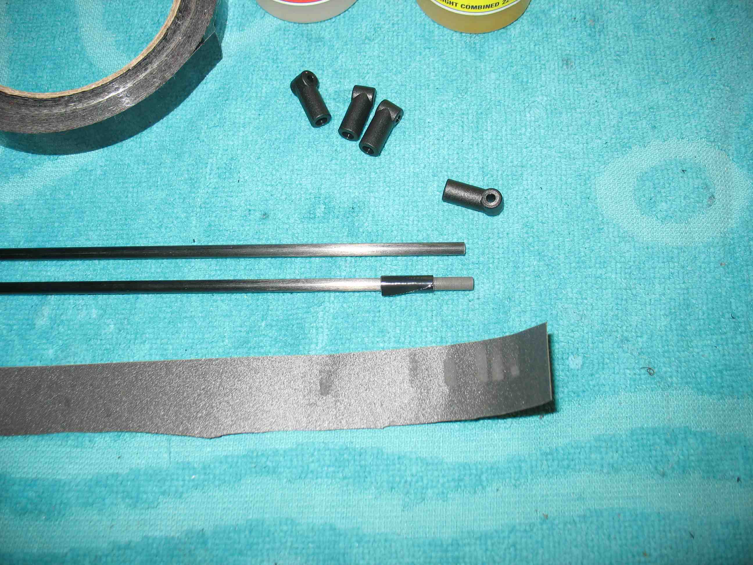 full resolution pic: http://rzavelli.home.xs4all.nl/stuff...s/IMG_2337.JPG A picture of the assembled tail: 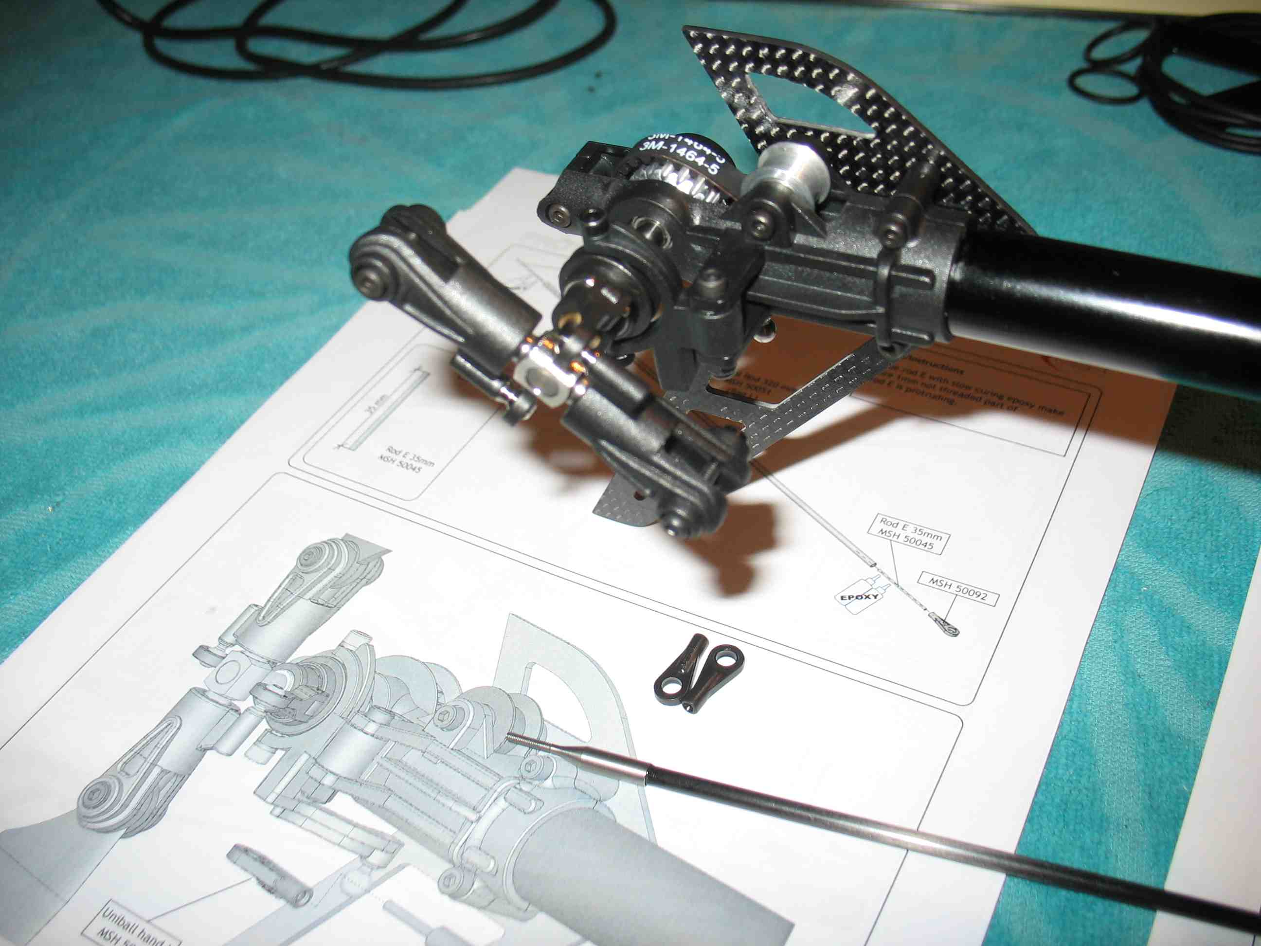 full resolution pic: http://rzavelli.home.xs4all.nl/stuff...s/IMG_2349.JPG I don't particular like the two blade grip ball joints in this pitch link system. This means there are three points on a single line, meaning, if every part isn't exactly nominal, the assembly will be over constrained. This may translate to increased tail slider drag. However, if it works, it works. Ever since I had the hub set screw of the Goblin 700 backing out, with it just hanging on to the crater in the shaft, preventing disaster, I just mount hubs completely with set screws and green fitting retaining compound to the tail shaft. This is a stock tail, using tail blade grips lacking thrust bearings. An upgraded thrusted version is available. The Protos tail rod has been revised somewhere in time, it now features a cup style rod that goes over the carbon, similar to the Mini Protos. This solution eliminates the chance of splitting the end, likely with screwing a threaded rod into a hollow carbon rod. Next up are the motor, ESC and Mini V-Bar mounting. Ugh, a conflict in the manual, I didn't notice it earlier. Of course I picked the wrong orientation to optimize the original star shaped servo horn for. 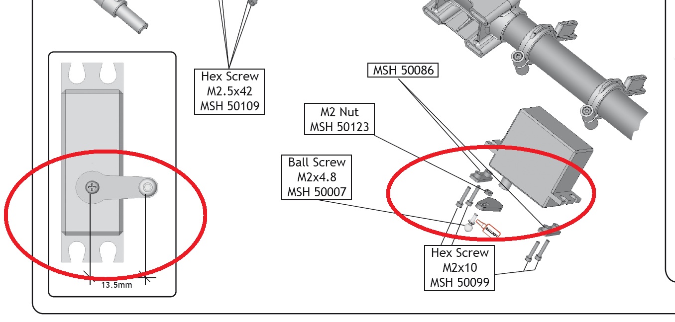 full resolution pic: http://rzavelli.home.xs4all.nl/stuff...n_conflict.jpg 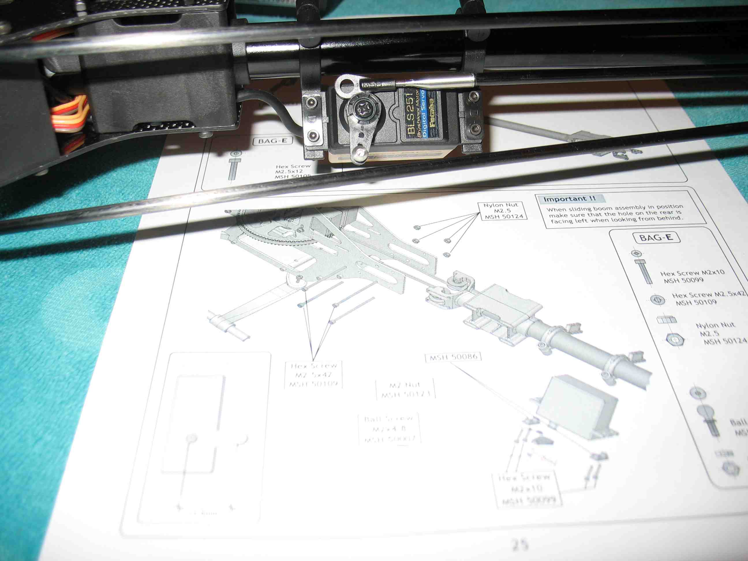 http://rzavelli.home.xs4all.nl/stuff...s/IMG_2354.JPG Unscrewing the servo horn, I was hoping the Futaba serration has an even number of splines, so the horn would rotate exactly 180°. Of course it didn't, ruining a perpendicular position at the opposite side. Fortunately I still have identical star shaped horns laying around, so I'll make a new one. full resolution pic: http://rzavelli.home.xs4all.nl/stuff...s/IMG_2261.JPG Stuff done during the weekend. Took the tail apart once more, since I noticed the tail servo wire mantle could rub against the inside edge of the large hole. So I took a wet file and chamfered the inside edge. 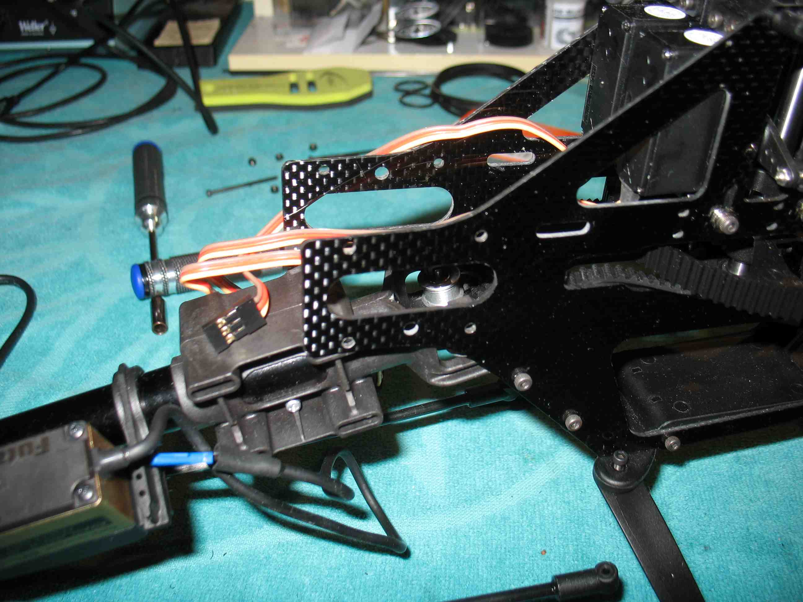 full resolution pic: http://rzavelli.home.xs4all.nl/stuff...s/IMG_2379.JPG Below a picture of the motor with the long shaft from the stretch kit mounted, featuring a 4mm end diameter. Displayed to the left, the original short motor shaft, the 5mm to 6mm pinion adapter and the stock non-stretch 6mm 15T pinion. To the right a PVC tube with parallel ends, used with an small arbor press to remove the original motor shaft. I then used an accurate drill press to mount the long one. In the middle, the 4mm 14T pinion from the stretch kit. Also shown, the 3rd motor bearing support and the drilling template plus drill, to modify old carbon fibre frame plates for the 3rd bearing support. All current CF frame plates already feature these holes. 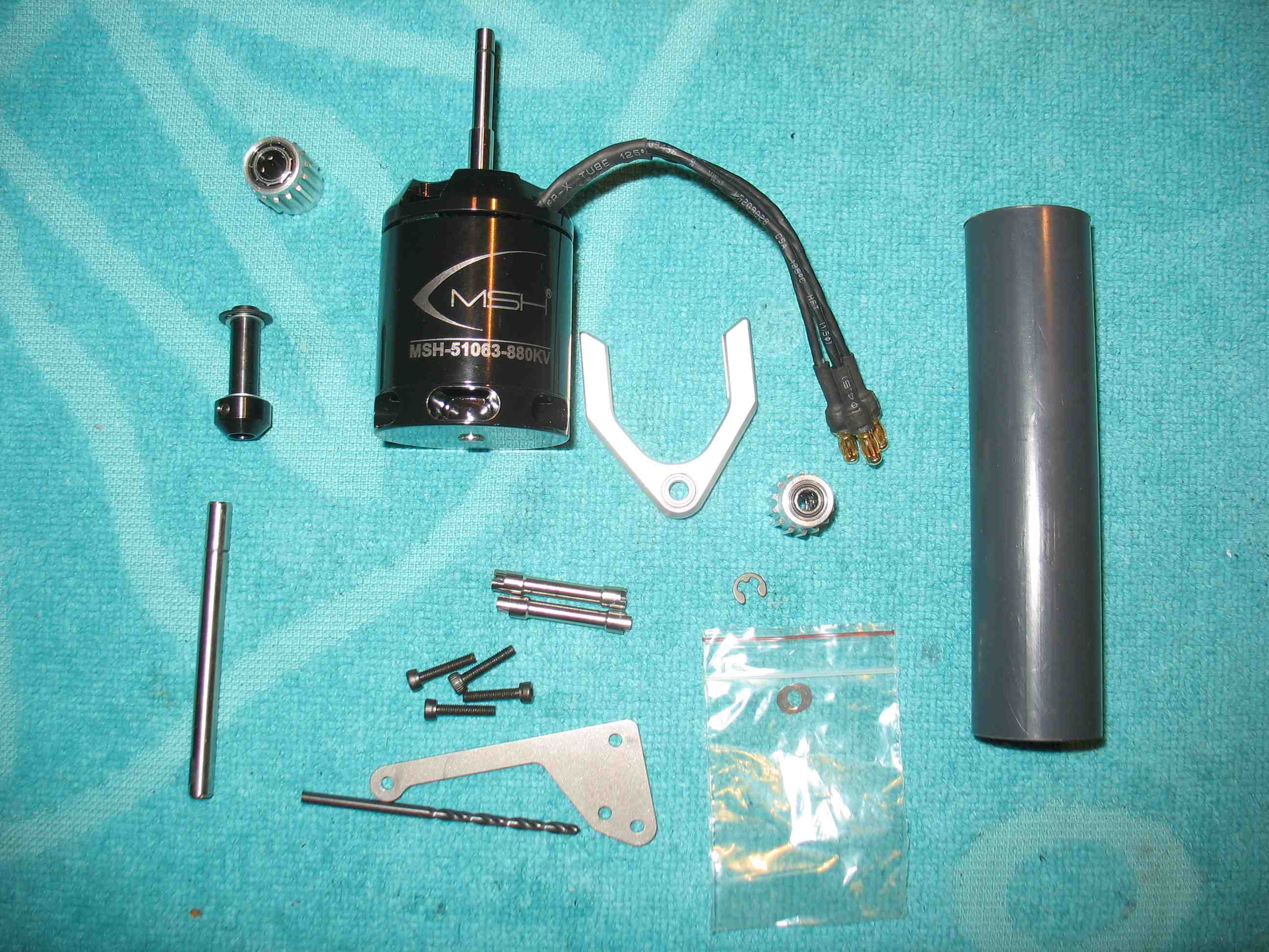 full resolution pic: http://rzavelli.home.xs4all.nl/stuff...s/IMG_2382.JPG My precious brand new YGE 80 LV, one of the last, it's out of production these days. I had this sent in to YGE, they modified it to include external governor support. Alternatives are the YGE 60 or the heavy YGE 90. 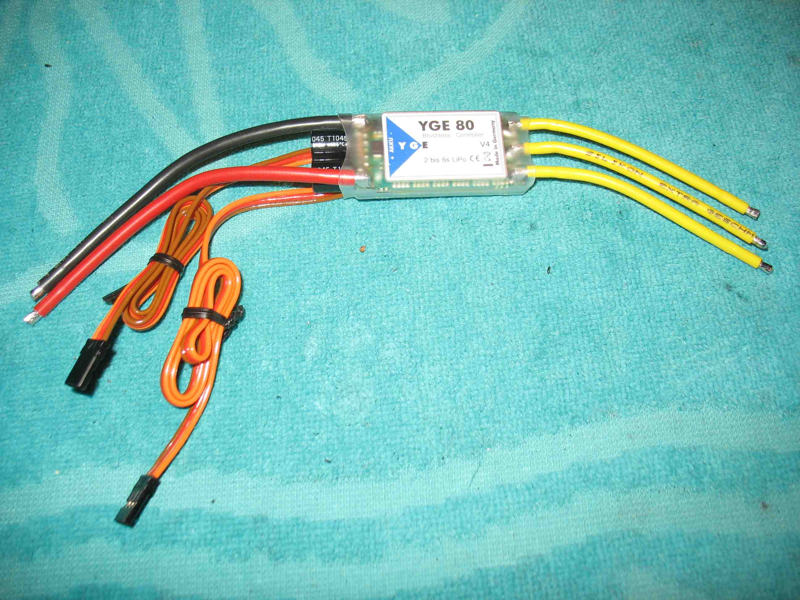 full resolution pic: http://rzavelli.home.xs4all.nl/stuff...s/IMG_2415.JPG Fairly hard to see, but notice the governor phase wire at the front. Only the signal and ground wire are connected to the board. 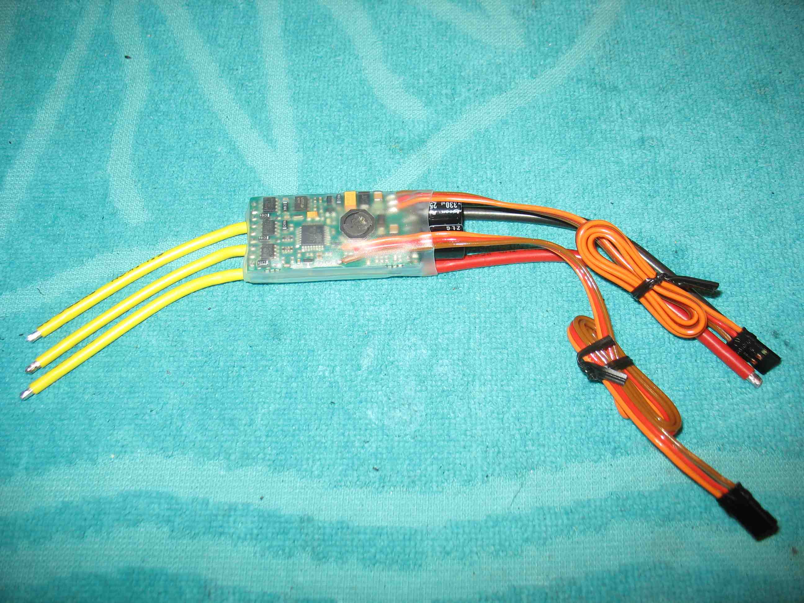 full resolution pic: http://rzavelli.home.xs4all.nl/stuff...s/IMG_2424.JPG Now, let's take a look at the wiring diagram of the Mikado Mini V-Bar, straight from the Mikado vstabi.info website:  "RX A = triple I/O, do not use for RC voltage!" "All others: brown/black wire pointing towards the upper (label) side. " So, the RXA port features three signal pins, the top one being used for the ESC phase input signal. In other words, the ground on the ESC governor wire should be useless in conjunction with a Mini V-Bar, right? Correct. For my Mini Protos YGE 60 LV with external governor support, I contacted Heino Jung at YGE, asking whether it was allowed to remove the brown ground wire and red wire completely. He confirmed the governor was ground internally and it was ok to remove those two wires, so I did. For this new YGE 80 LV, I did the same. DISCLAIMER: Do this at your own risk, only on the current YGE LV models in conjunction with current Mini V-Bar models. If your complete heli somehow explodes after you've done this, don't come and blame me or YGE. Next up a picture of my soldered YGE 80 LV and motor. EC3 for battery connections, ESC motor wires shortened and EC3 sockets soldered. The brown and red governor wires were only partially removed. The remaining bits are retained for mitigation of occasional forces on the signal wire's board solder joint, nothing else. I moved the pin location of the governor signal wire in the connector from the bottom to the upper position, since it's the upper pin of the Mini V-Bar RXA port that's used for governor phase input. I replaced the shrink wrap on the motor's plugs, since they were partially exposed when connected to the ESC. The stock M3x8 screws with washers were a bit on the long side, with the possible chance of the internal motor wires rubbing against the end of one of the screws, risking shortage over time. So I opted for shorter screws to mount the motor. 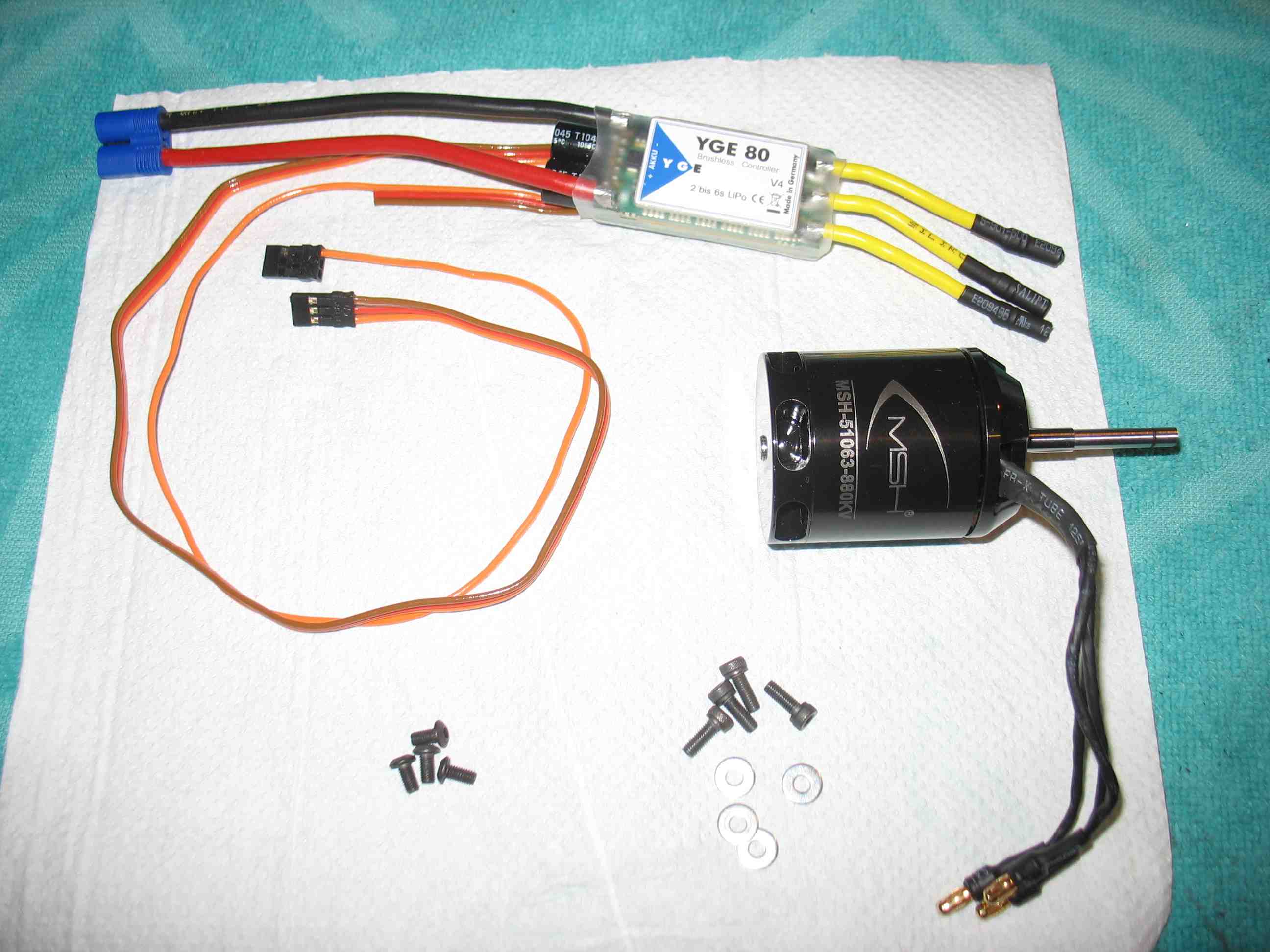 full resolution pic: http://rzavelli.home.xs4all.nl/stuff...s/IMG_2431.JPG Mounted the motor, notice how the 3rd bearing support has slots. The reason for this is that owners of old Protos carbon frames have to modify their frames to mount a 3rd bearing support. Drilling holes using a template is the easiest solution here, hence the slots in the support. The later released Mini Protos features slots in the frames and threaded holes in the support. The rotating E-clip that's supposed to be mounted above the pinion, has a 7mm outer diameter, this allows it to rub against the stationary outer ring of the 3rd bearing. Included in the stretch kit was an extra undocumented pinion shim, so I placed this extra shim above the E-clip, prior placing the 3rd bearing support. This avoids the rotating E-clip from rubbing against the stationary 3rd bearing outer ring. It's best to mount the 3rd bearing support with the belt removed from the main pulley, so the motor shaft is relieved of any stress caused by belt tension. This ensures prefect coaxial alignment of the 3rd bearing with the motor bearings. After fixating the support, reinstall the belt onto the main pulley. 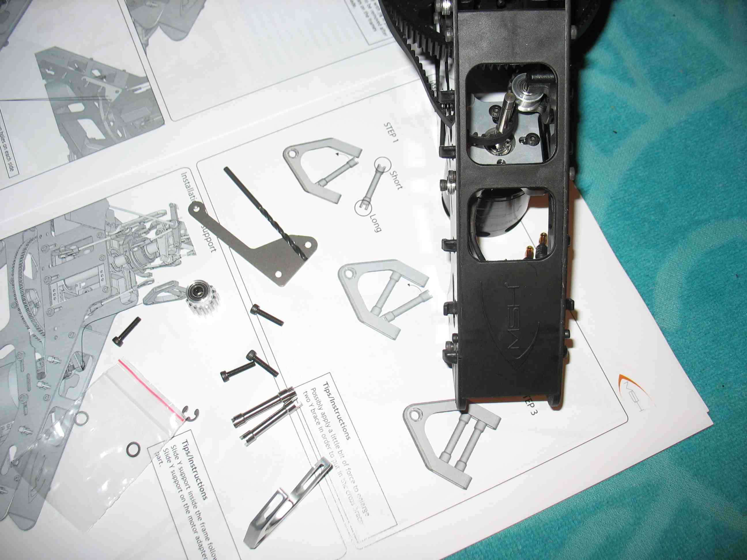 full resolution pic: http://rzavelli.home.xs4all.nl/stuff...s/IMG_2451.JPG ESC installed and wires routed. Remember when I mentioned I didn't thread lock the bottom plate yet? Here's the reason, clear access to everything ESC wise. At this point I also remembered I had a motor wire on my Mini Protos damaged from chafing after about 600 flights, against the frame plate hole for the ESC retaining rubber band. Used a wet file again to chamfer the inside edges of the CF frame plate rubber band holes. 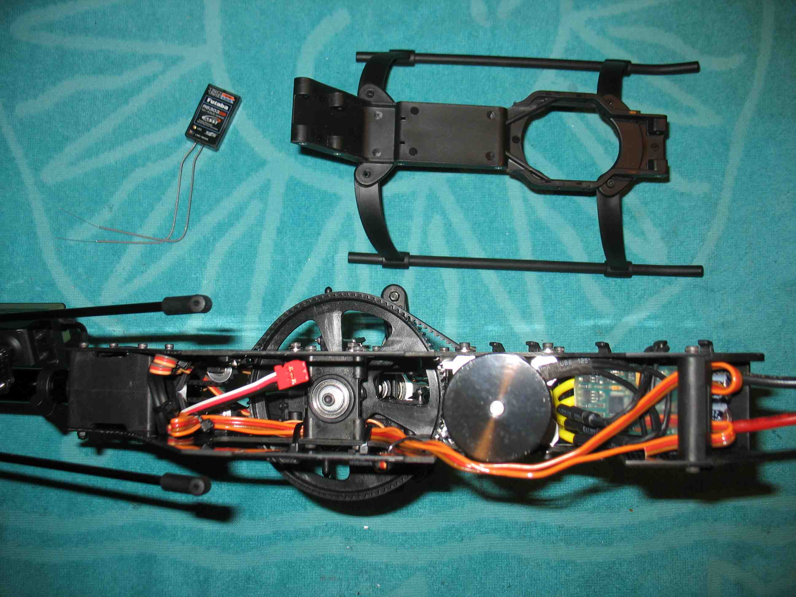 full resolution pic: http://rzavelli.home.xs4all.nl/stuff...s/IMG_2478.JPG
__________________
RAW 420 / RAW 580 / Kraken 580 Nitro / Goblin 700 / 2x RAW 700 / Kraken 700 S VBC-t & Neo Pro / Scorpion motors & ESCs / MKS HBL575 SL & HBL980 / Supra X D4, D6 & S6 / OptiPower / Revolectrix 2x Bump & 5x PL8v2 https://www.youtube.com/kjoer |

|


|
| Sponsored Links | |||
|
Advertisement |
|
||
|
08-13-2015, 09:52 AM
|
#62 (permalink) |
|
Registered Users
Thread Starter
Join Date: Sep 2011
Location: The Netherlands
|
And here is part two of all the posts, with revised url's:
Ugh, just found out my two year old tube of Shoe Goo aged. The stuff got really thick. Was going to use it for preventive canopy grommet area reinforcement. Edit: Tube turns out to be six years old. Arf. CA-ed the canopy grommets in place nevertheless, using a needle on the inside of the grommets, mitigating stress caused by placing and removing the canopy. Needs some fresh Shoe Goo now to reinforce it a bit. The (Mini) Protos canopy is pretty weak in the grommet area. Antenna guidance on both helis, nothing special here. Bit of hotglue to fixate them. 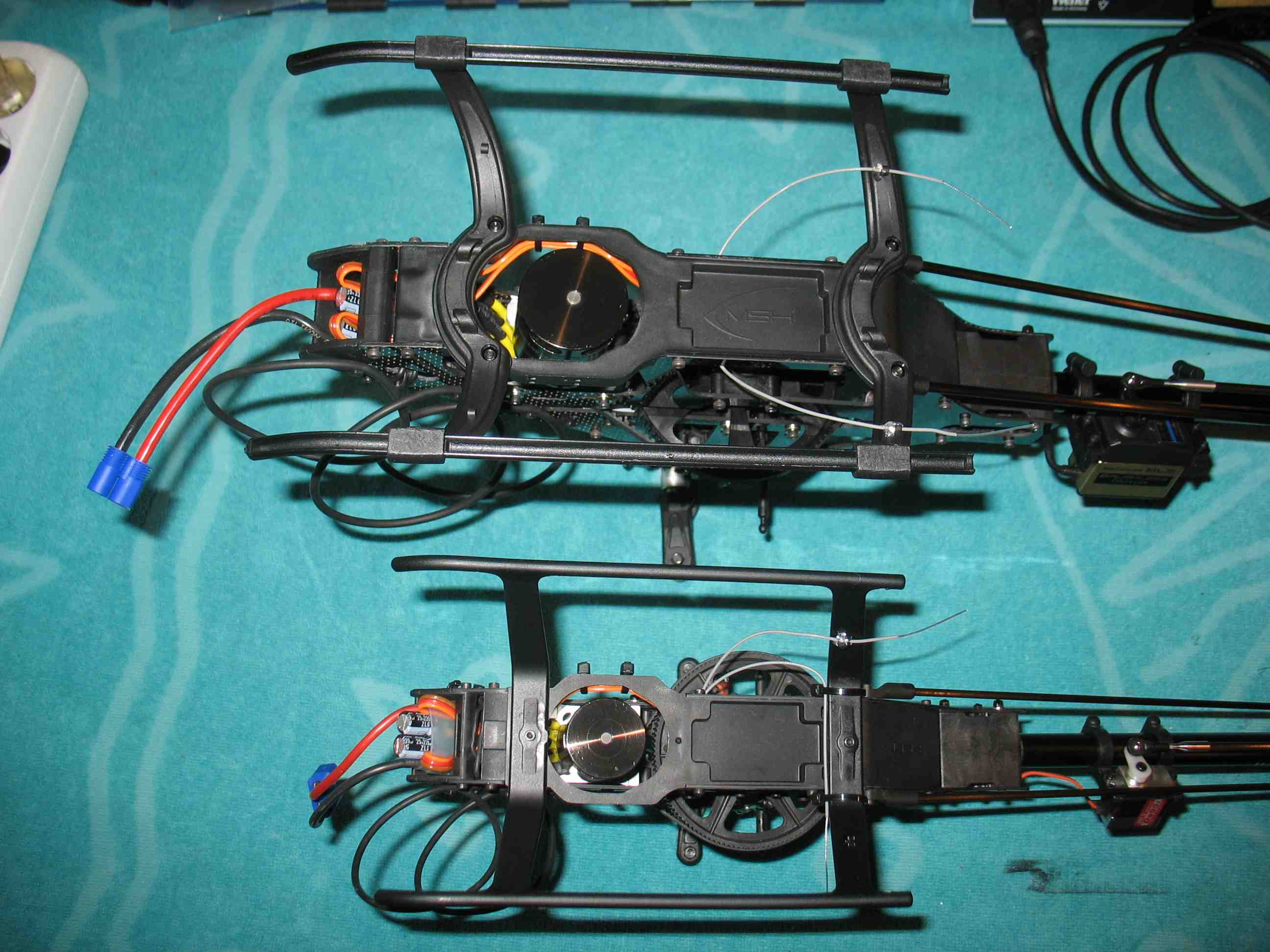 full resolution pic: http://rzavelli.home.xs4all.nl/stuff...s/IMG_2545.JPG Set the YGE end points using the transmitter with a 0-100% normal throttle curve, V-Bar gov initially off. Checked the ESC led turned off at full stick, confirming the ESC is providing full throttle. Then used a ProgCard II for the following settings: timing: 18 degrees brake: off cut off type/accutype: slow down/LiPo cut off voltage: 3.1V cells: 6 special functions: nothing act. freewh./gov. mode: freewh. on/gov. off gov. mode P-gain: 0.9 gov. mode I-gain: 0.05 startup speed/gov.mode: plane fast + 3x gov. off + plane fast (external gov.) PWM-frequency: 8kHz startup power: auto 1-32% plane fast + 3x gov. off + plane fast means I have plane fast response in both the 0-75% and 75%-100% throttle bands of the ESC. This allows you to run low headspeeds with high gain values if you ever feel like it (provided you don't fry the ESC in the process). Note: these 0-75% and 75%-100% values don't correlate with the transmitter values used for the V-Bar gov. Soft-start and spool-up will be handled by the V-Bar gov. Works well for me. Mini V-Bar installed. On my Mini Protos I dare to fly without hotglue on the connectors, since they're self-locking, due to the wire curve paths back down the tail mount. On the Protos the connectors are far from self-locking, so I went for the standard hotglue procedure there. The difference in tail servo size still baffles me, but apparently this is the way to go on both helicopters. 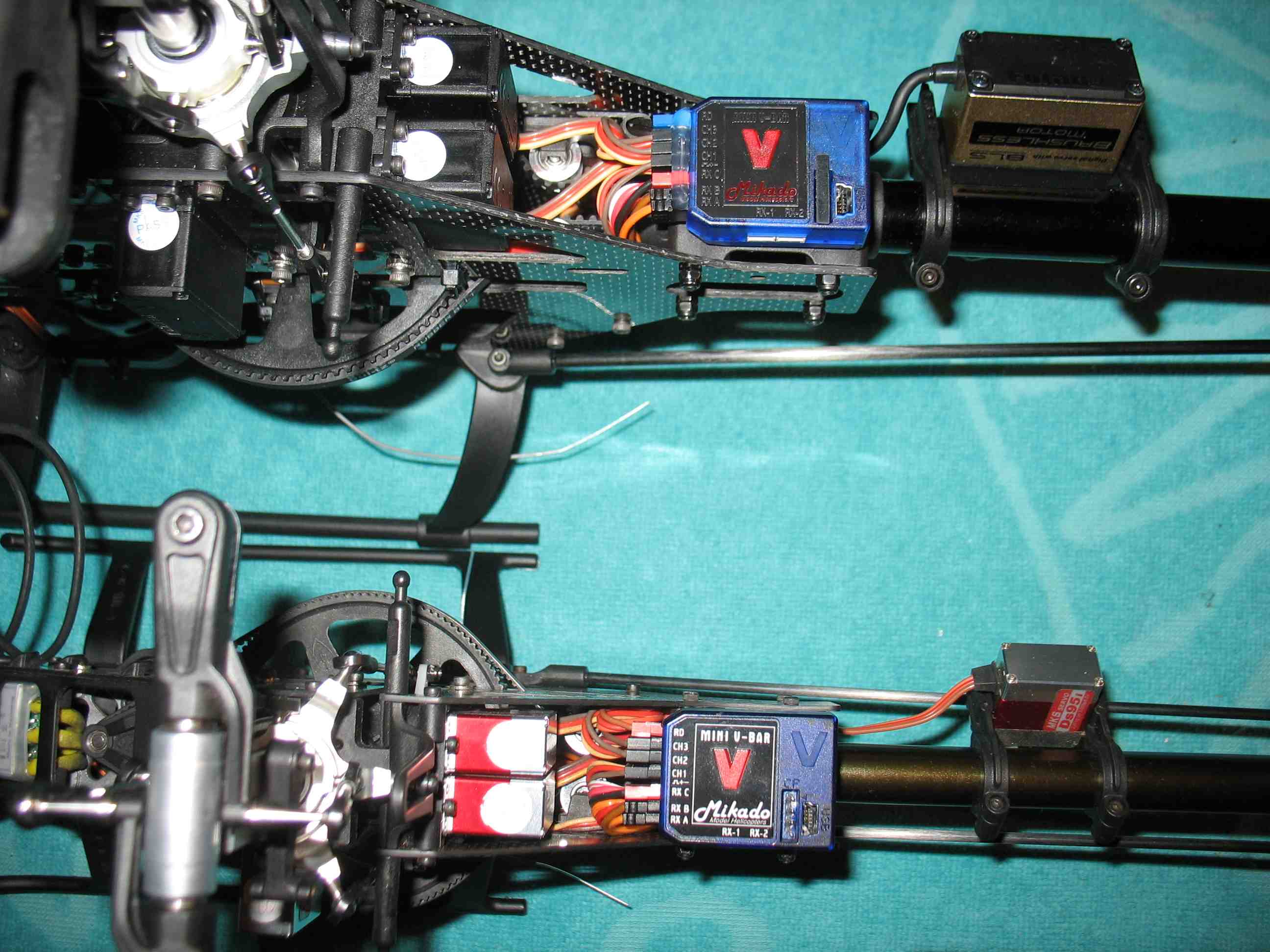 full resolution pic: http://rzavelli.home.xs4all.nl/stuff...s/IMG_2534.JPG Note how the newer Mini V-Bar on the Protos has a different label. In my vstabi.info customer device info, it comes across as a "Singlesensor" version. I suspect it corresponds with the new label, introduced somewhere last year, if I'm not mistaken. I'm going to address the V-Bar governor a bit, not Protos related, but it's a hot item. First the obvious stuff. Governor basic settings I:  Governor basic settings II:  Max. Headspeed should be a sensible value, but it doesn't necessarily mean the helicopter will or should be able to reach this headspeed. It's only the headspeed the V-Bar gov will try to achieve, when the transmitter throttle curve is set to 100%. Gear Ratio is obvious. Sensor configuration being the motor pole count divided by two, the Scorpion motor in this case being a 10 pole motor, thus requiring a value of 5 to be entered. So, Protos transmission ratios and headspeeds. This is an Excel file I cooked up, not very scientific, but it should be close: Excel file download: http://rzavelli.home.xs4all.nl/stuff...ion_ratios.xls Now, I was tired of the empirical determining the throttle values to request a certain headspeed. The scales between the transmitter values and the internal V-Bar are different, the formula is simple. Let's say we enter a max heaspeed of 3000 in the V-Bar software, meaning the V-Bar gov will try and achieve a headspeed of 3000, when it receives a full (100%) throttle value from the transmitter. Suppose we want a certain headspeed value in idle2, let's say 2645. (2645/3000)*50+50=94.1 We would need a throttle curve of 94.1% to request a 2645 headspeed. So, I made a home brewed Excel file to calculate throttle values when requesting certain headspeeds:  Excel file download: http://rzavelli.home.xs4all.nl/stuff..._v-bar_gov.xls So basically, when I want to change an idleup mode to a certain headspeed, I simply calculate it with the Excel sheet. No verification without blades on the bench required. Here are my initial transmitter throttle curves for the maiden flight: normal (1500 rpm): 0.0 75.0 75.0 75.0 75.0 idle1 (2010 rpm): 83.5 83.5 83.5 83.5 83.5 idle2 (2400 rpm): 90.0 90.0 90.0 90.0 90.0 idle3 (2700 rpm): 95.0 95.0 95.0 95.0 95.0 More boring initial V-Bar gov settings:   Enough boring writing and reading, back to pictures, build complete! Left side: 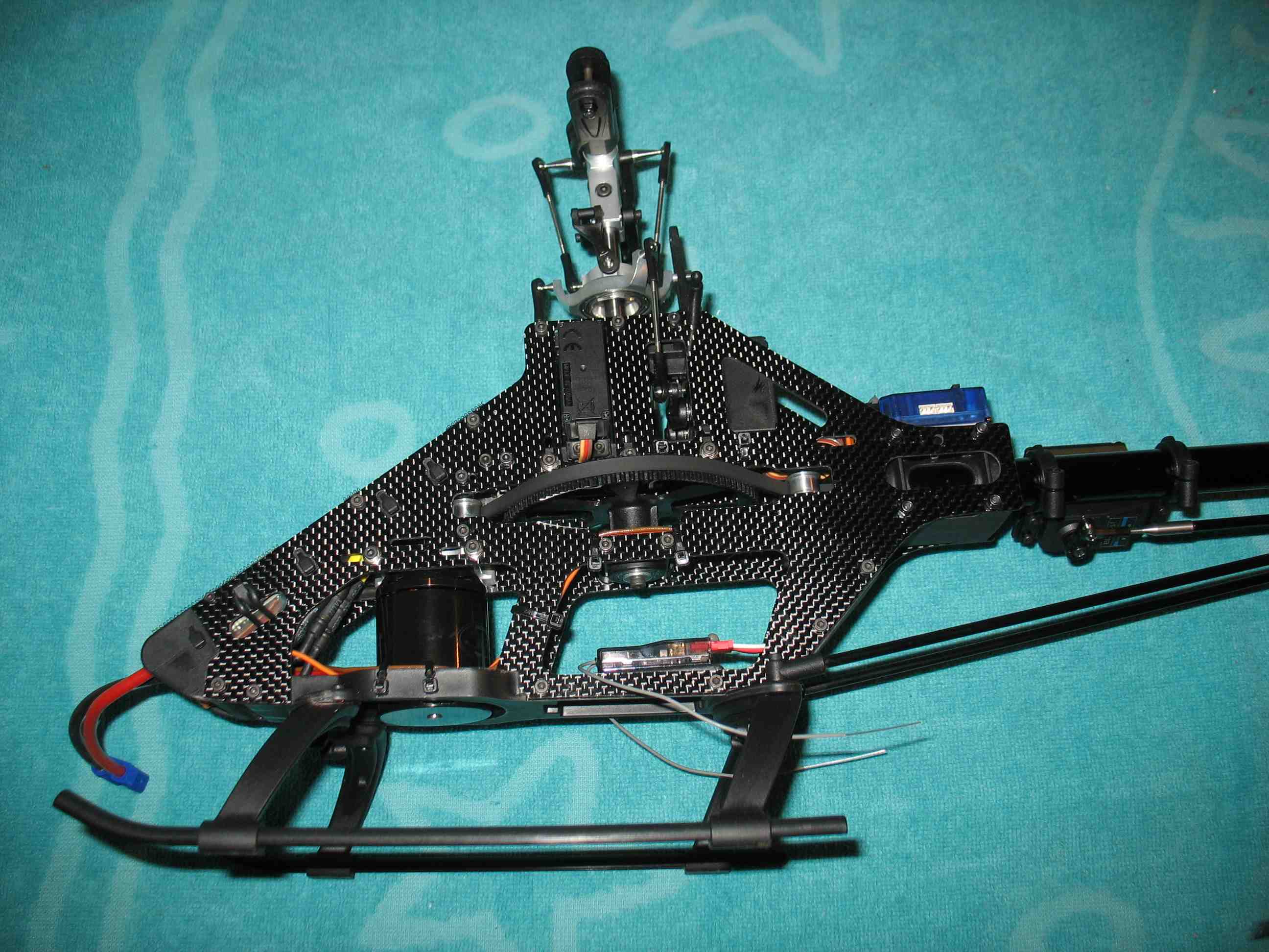 full resolution pic: http://rzavelli.home.xs4all.nl/stuff...s/IMG_2557.JPG Right side: 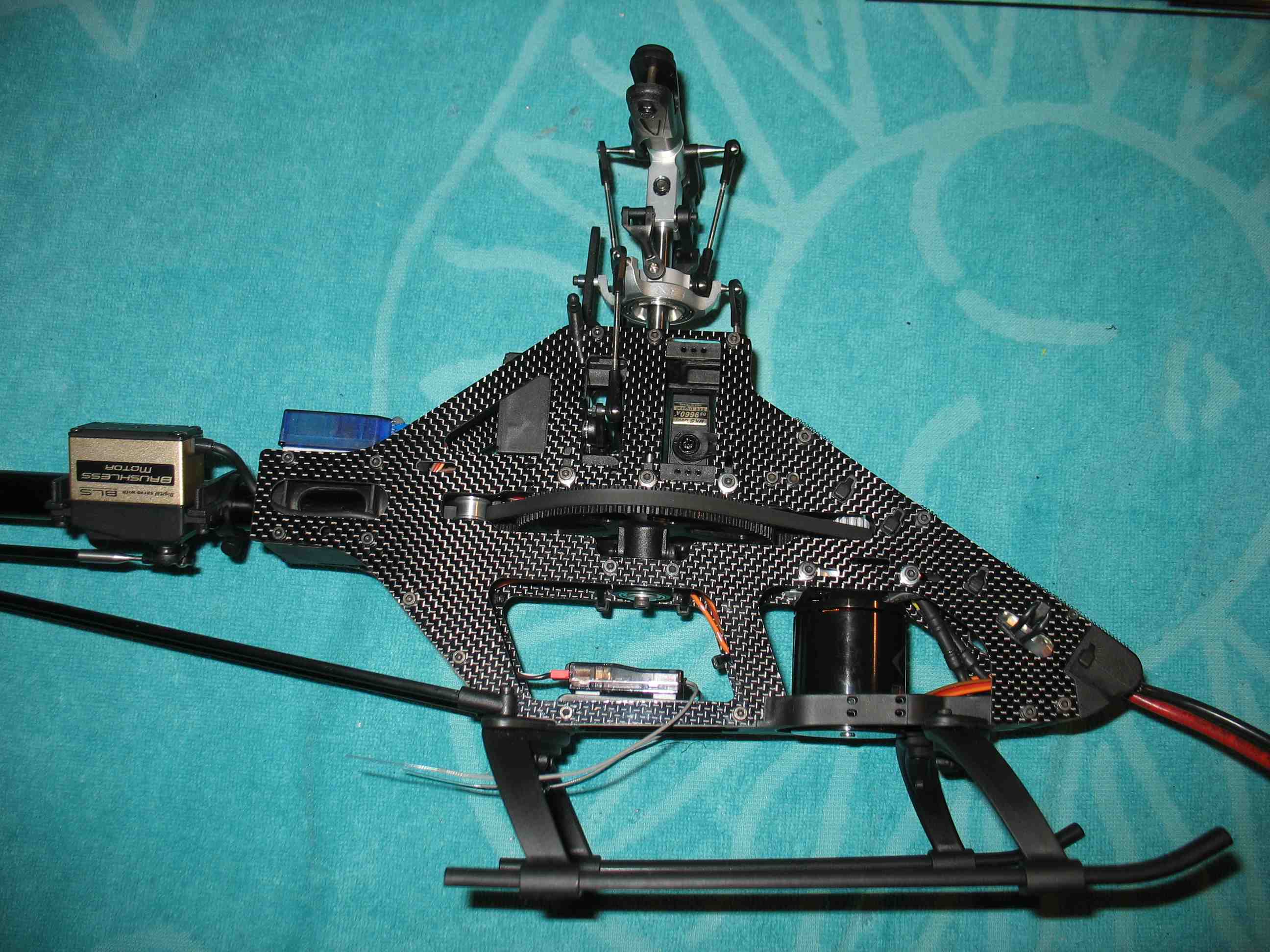 full resolution pic: http://rzavelli.home.xs4all.nl/stuff...s/IMG_2563.JPG I have the canopy posts in the standard rear position on the Protos. Works great with the 2700mAh LiPo I have at the moment. CG is perfect and canopy fits perfectly. Any increase in LiPo size and I'll have to move the posts forward though, for canopy clearance. The top bit of LiPo hook-and-loop fastener doesn't serve a function at the moment, my current LiPo stays clear of that. 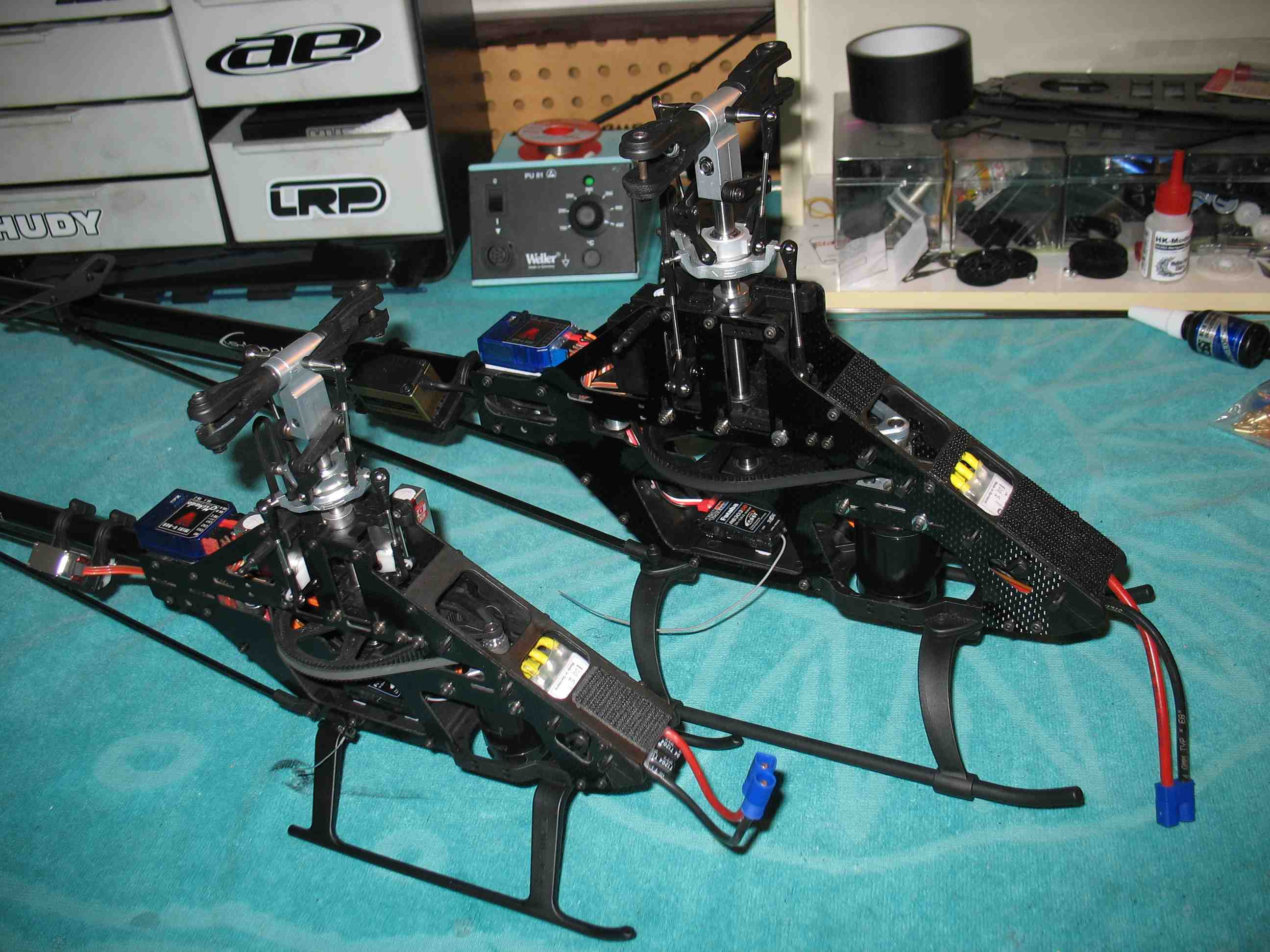 full resolution pic: http://rzavelli.home.xs4all.nl/stuff...s/IMG_2617.JPG As I was writing this post, I realized the orientation of the swash driver arms is different between the two: 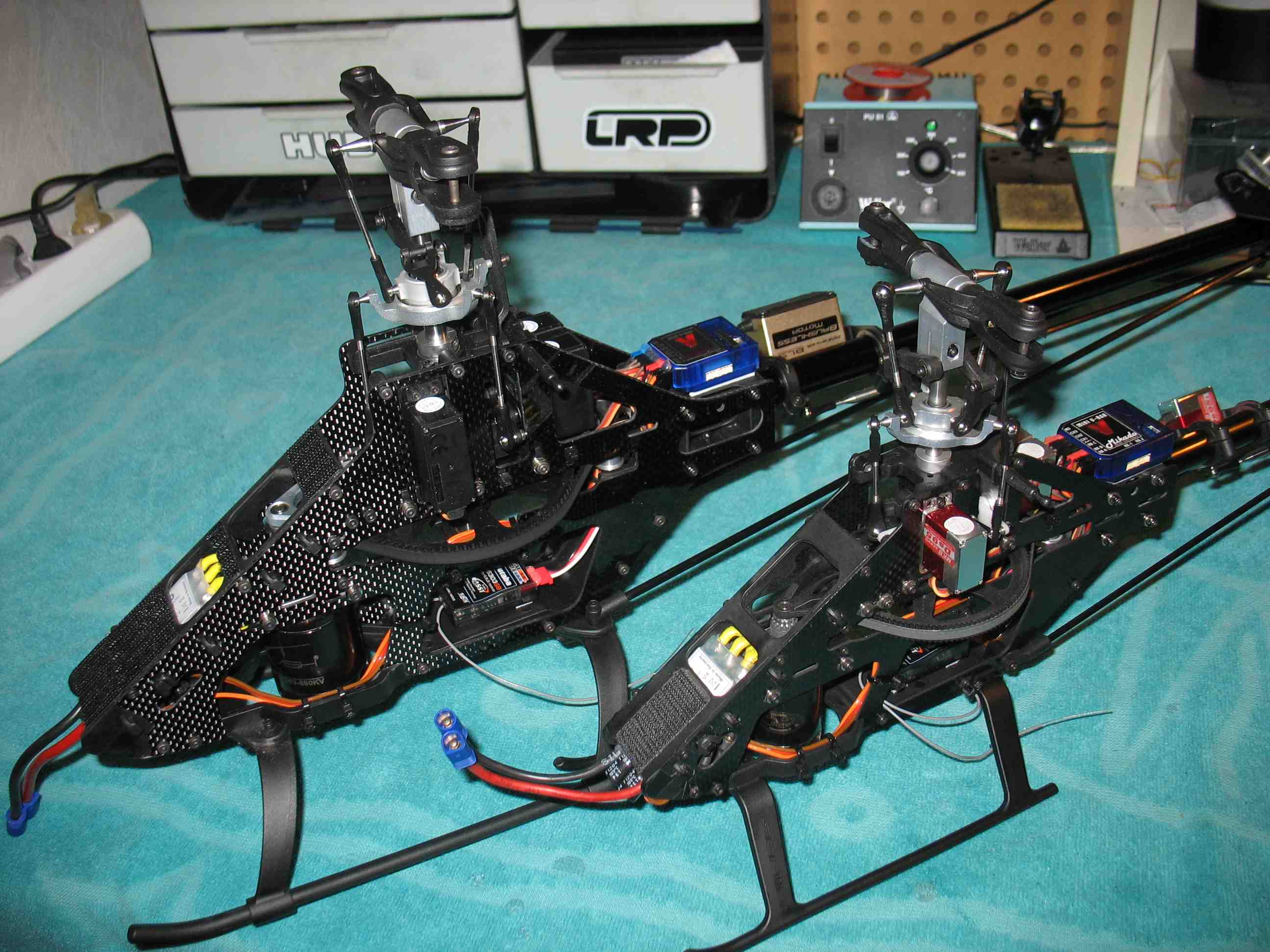 full resolution pic: http://rzavelli.home.xs4all.nl/stuff...s/IMG_2620.JPG Note the different tail pitch slider designs too: 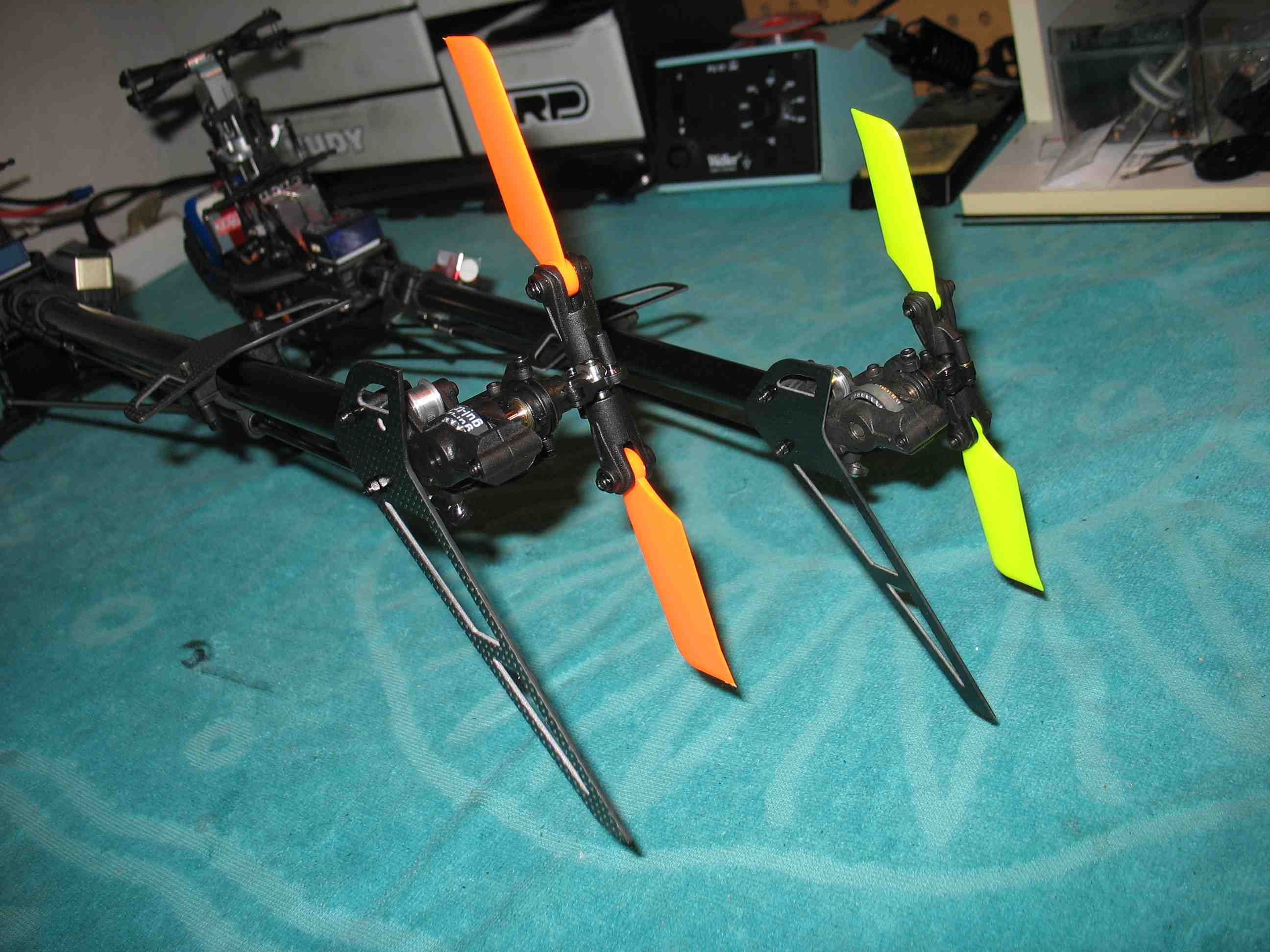 full resolution pic: http://rzavelli.home.xs4all.nl/stuff...s/IMG_2625.JPG The canopy reinforcement. CA on the inside of the grommet, followed by a 1-2mm rubber glue layer over the grommet area. 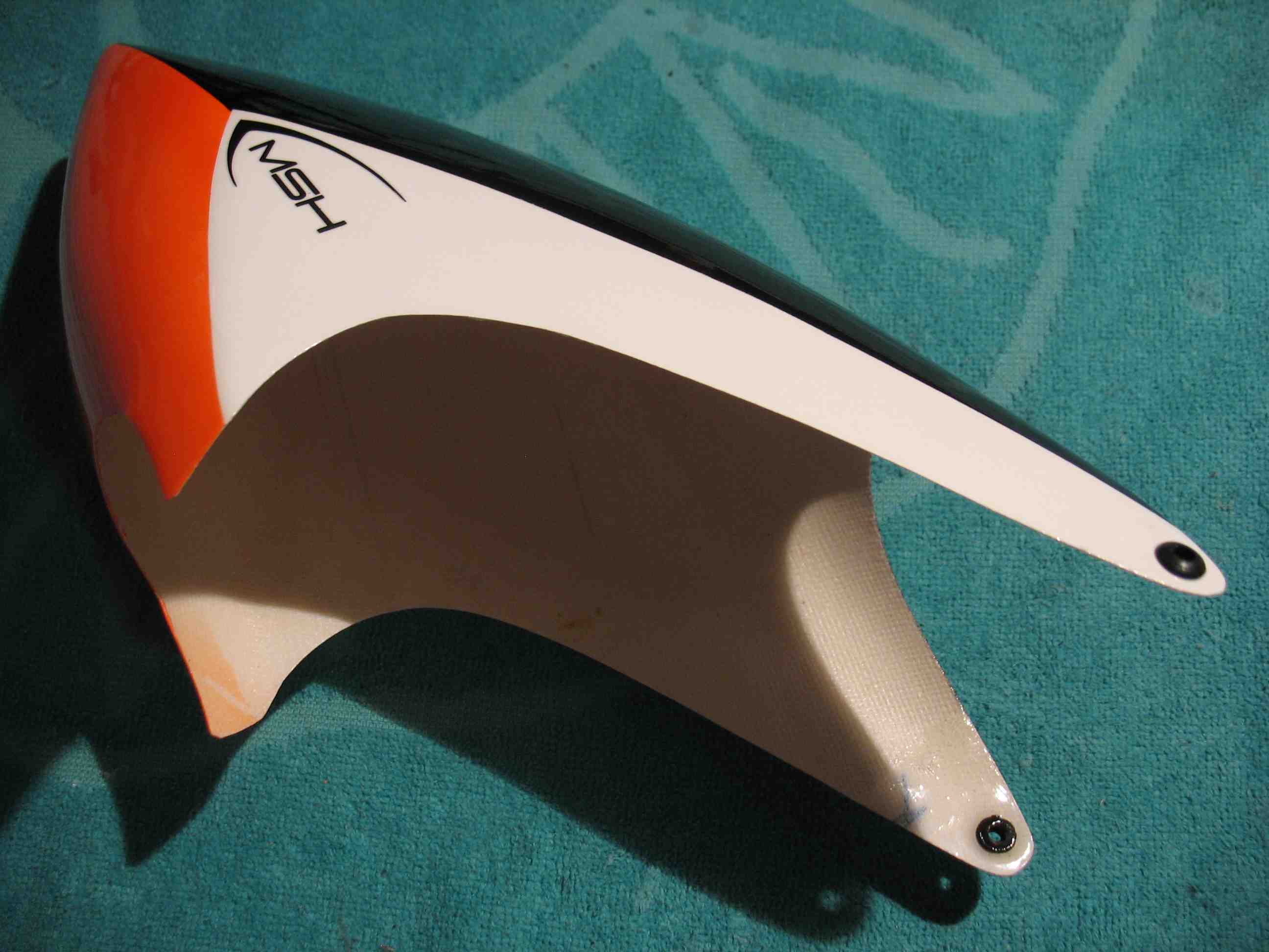 full resolution pic: http://rzavelli.home.xs4all.nl/stuff...s/IMG_2689.JPG 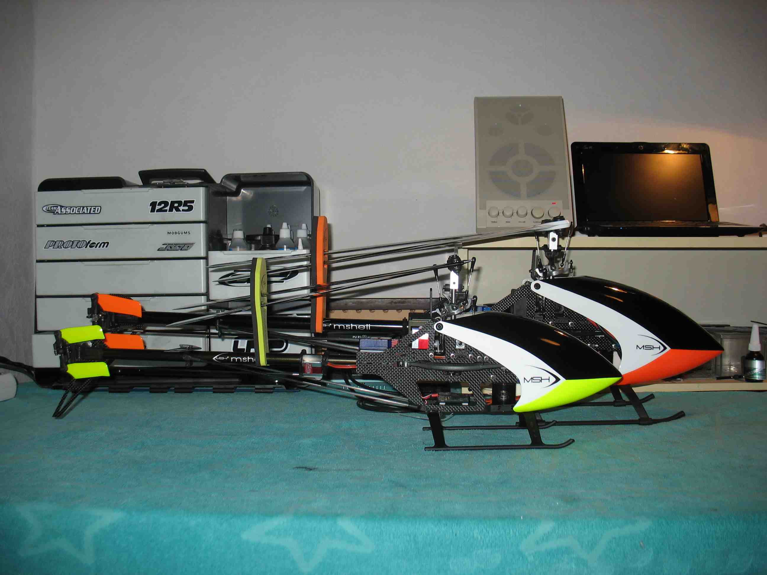 full resolution pic: http://rzavelli.home.xs4all.nl/stuff...s/IMG_2667.JPG 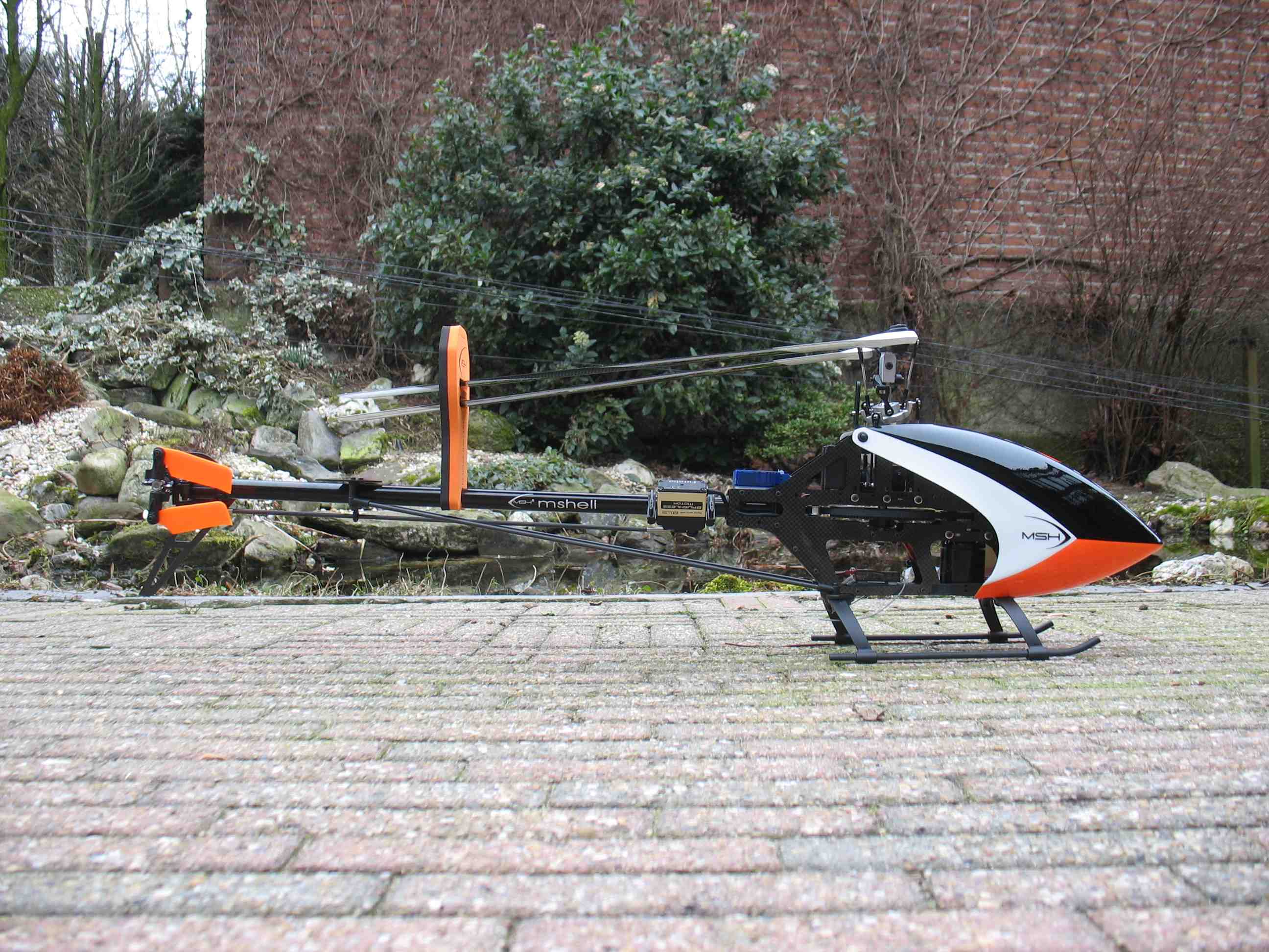 full resolution pic: http://rzavelli.home.xs4all.nl/stuff...s/IMG_2745.JPG 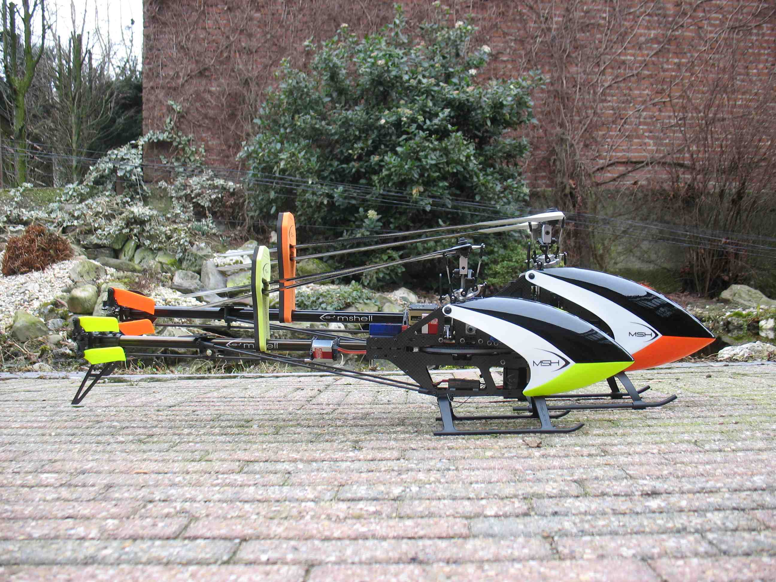 full resolution pic: http://rzavelli.home.xs4all.nl/stuff...s/IMG_2738.JPG 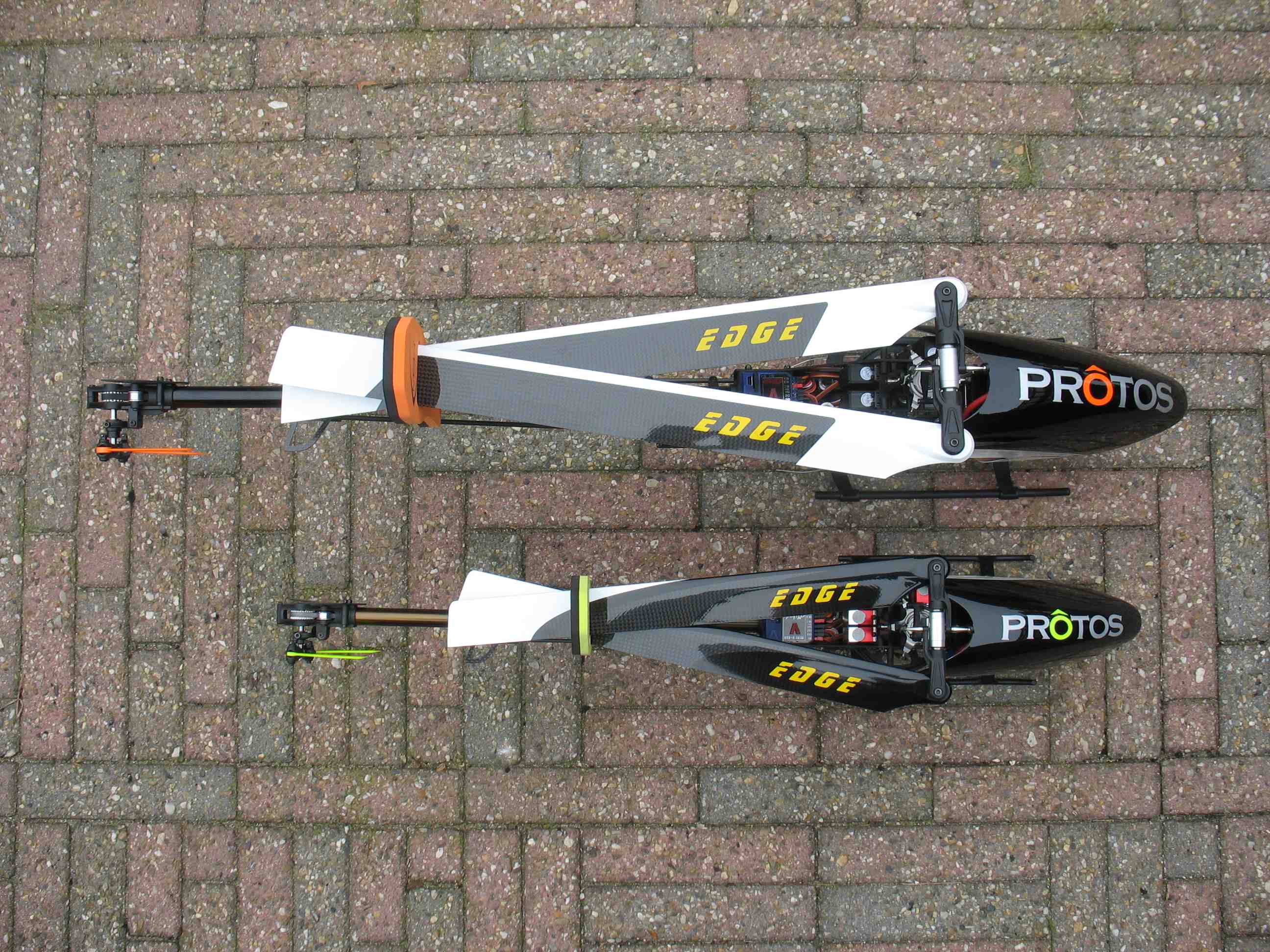 full resolution pic: http://rzavelli.home.xs4all.nl/stuff...s/IMG_2757.JPG Maiden flight: 2nd flight: Loving it so far, still have to change a couple of things though . Thought I should share some more from that maiden day. I dumb-thumbed (my first) it in its third flight overall, that same day. Result: Not simming or flying for three weeks probably being the root cause. In my 19 months flying career, including four months of mCP X, this is my third major crash in total. One with the Mini Protos, one with the Goblin 700 and now one with the Protos. So I can live with it. At least now I know how to build a Protos . A quick calculation and me hating to puzzle, made me order a new kit with all the option parts one day later. Rekit. I've ordered a naked Protos carbon FBL kit at Fast Lad. Received it on Wednesday. Turned out it's a normal kit, with the box seal broken and the FBL upgrade tossed in the box. Flybar parts are still included. More info about the crash and new build following. I'm gonna change two things in the new build. I've got three sets of new blades (SAB 465, Edge 473 and SpinBlades 465), so for that part I'm sorted for at least the next nine flights. Well, two weeks since the maiden and crash. Been to ROTOR live 2013 in Germany last weekend. Just reviewed the damage again, even though I have a fresh kit at hand. Wreck assessment, don't we all love it? I'll share the fun. Note the grass on the lower left corner of the LiPo mount: 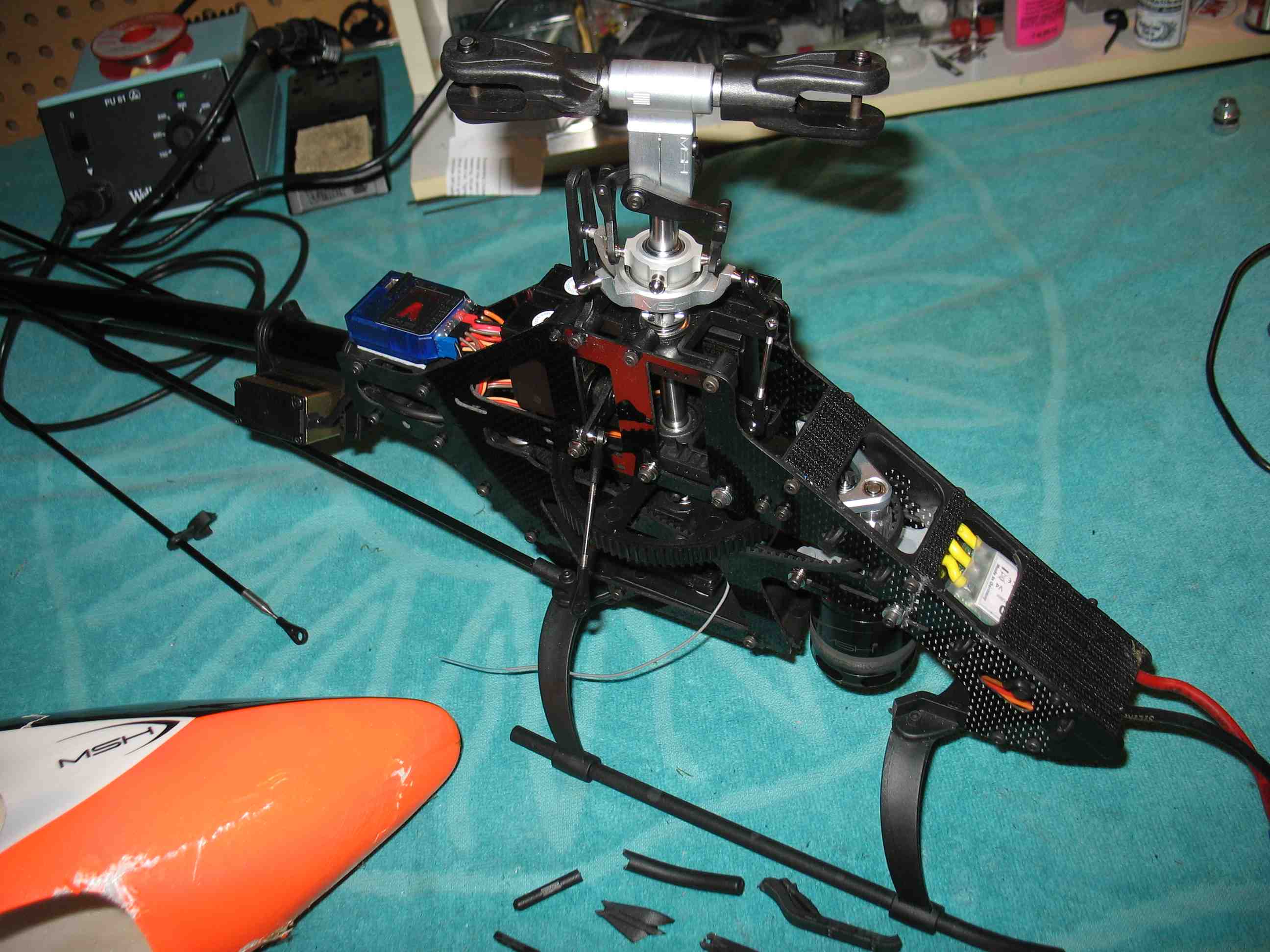 full resolution pic: http://rzavelli.home.xs4all.nl/stuff...s/IMG_2767.JPG The corresponding hole where it came through: 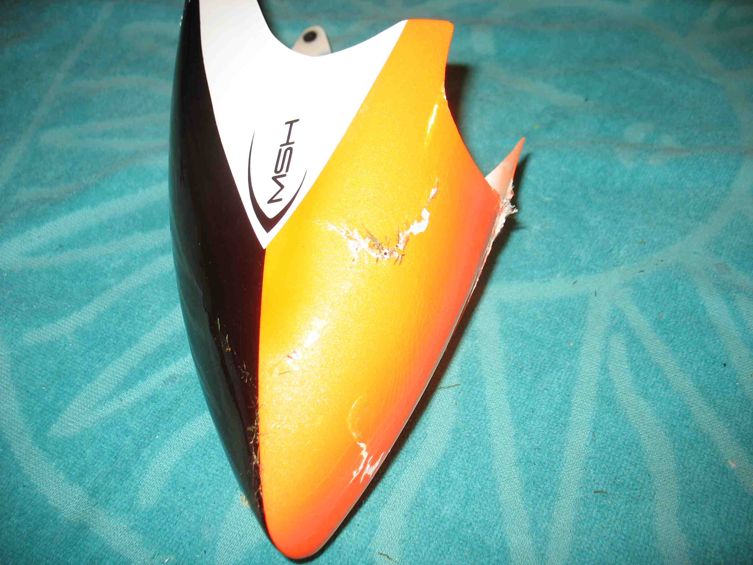 full resolution pic: http://rzavelli.home.xs4all.nl/stuff...s/IMG_2773.JPG 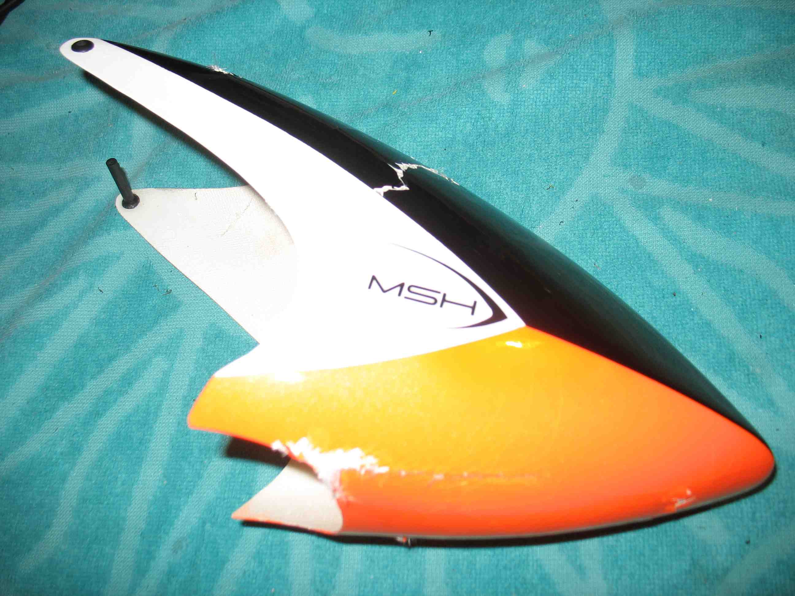 full resolution pic: http://rzavelli.home.xs4all.nl/stuff...s/IMG_2775.JPG It hurts: 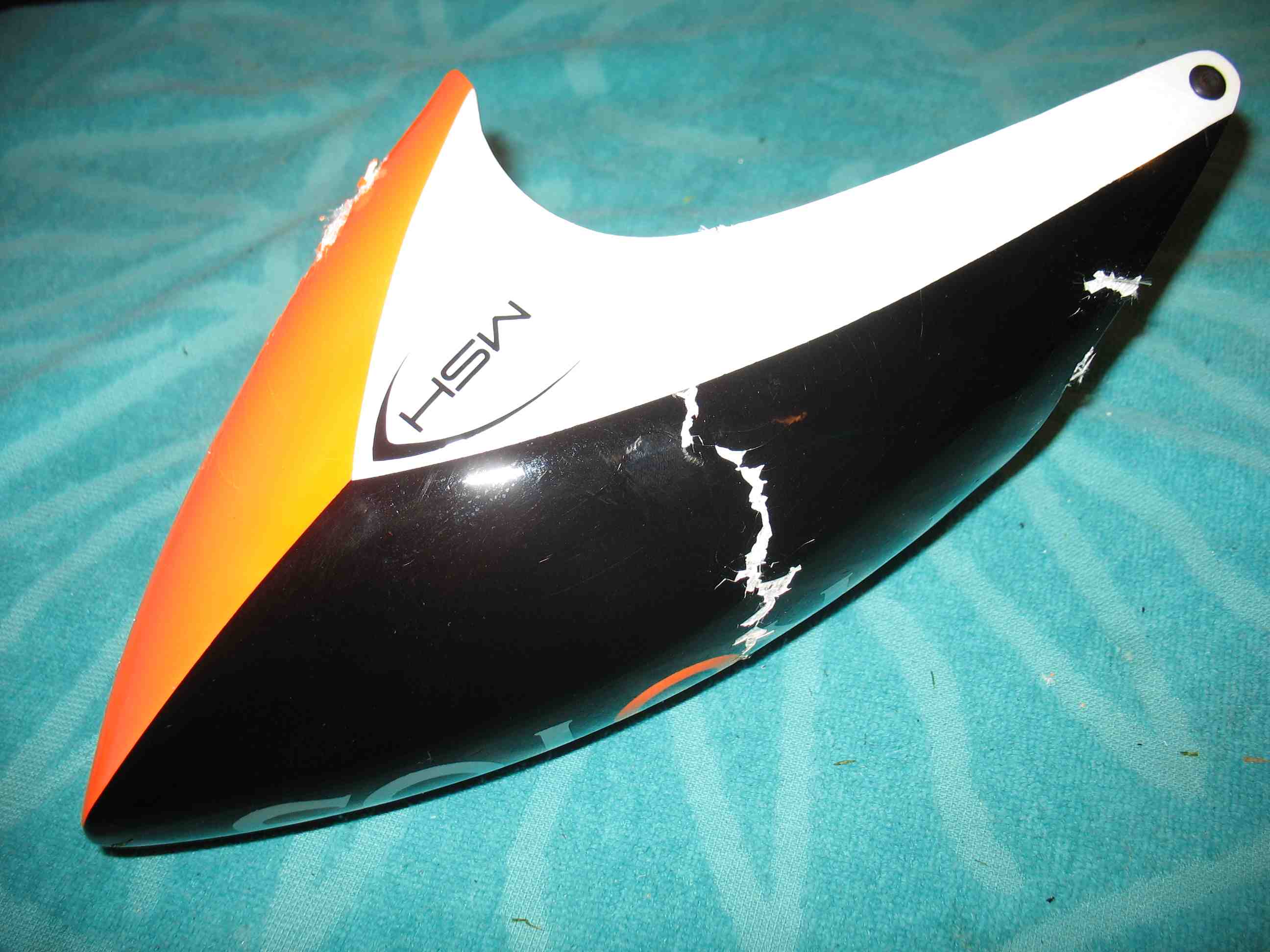 full resolution pic: http://rzavelli.home.xs4all.nl/stuff...s/IMG_2780.JPG Bent main shaft, needless to say everything in the head is toast too: 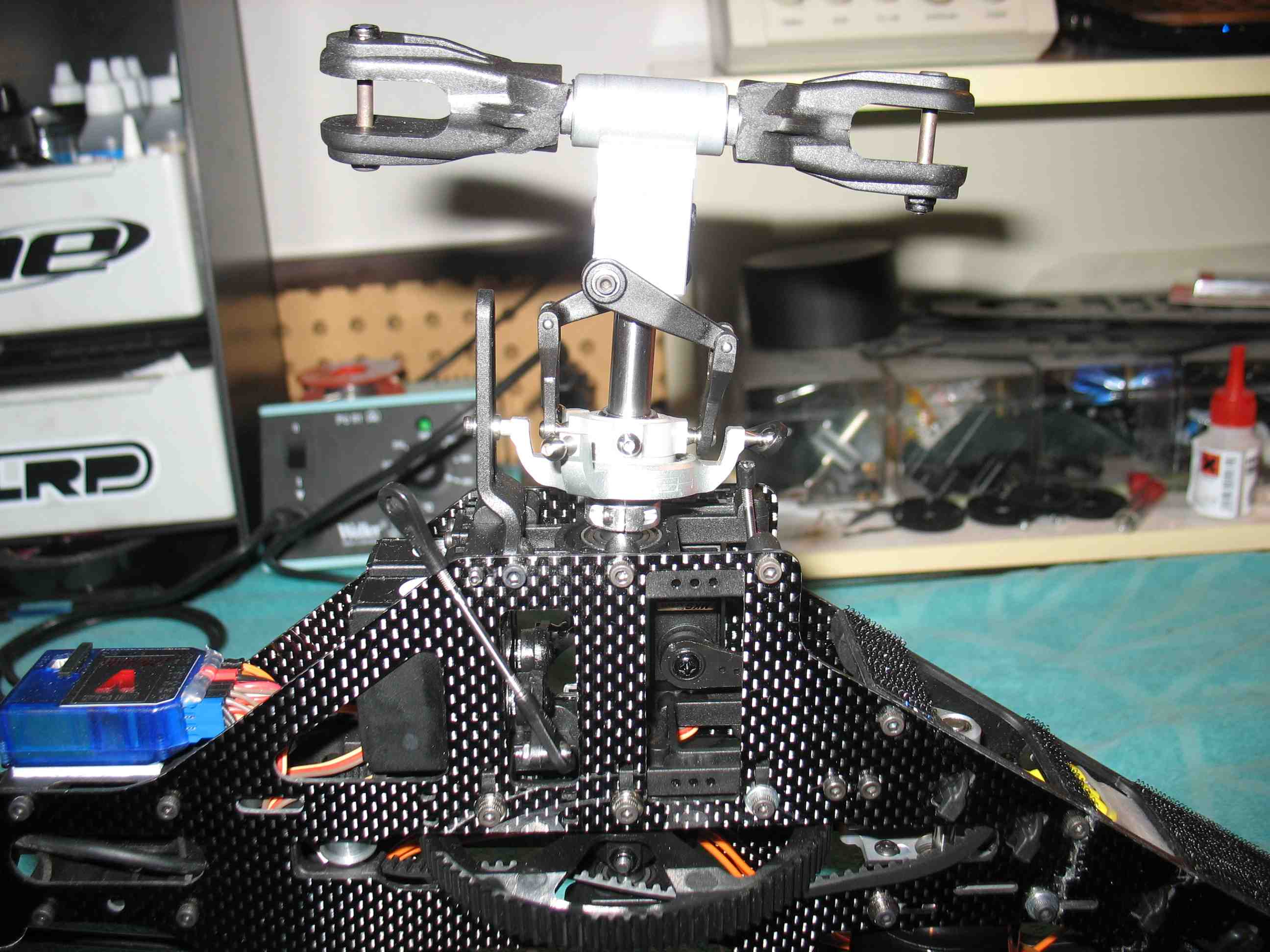 full resolution pic: http://rzavelli.home.xs4all.nl/stuff...s/IMG_2784.JPG I was told the servo mount/main shaft bearing blocks have a high chance of breaking too. Mains shaft bearings themselves are toast too ofc. Front swash link joint broke. Good thing links and blade grips break, hopefully saving the servos: 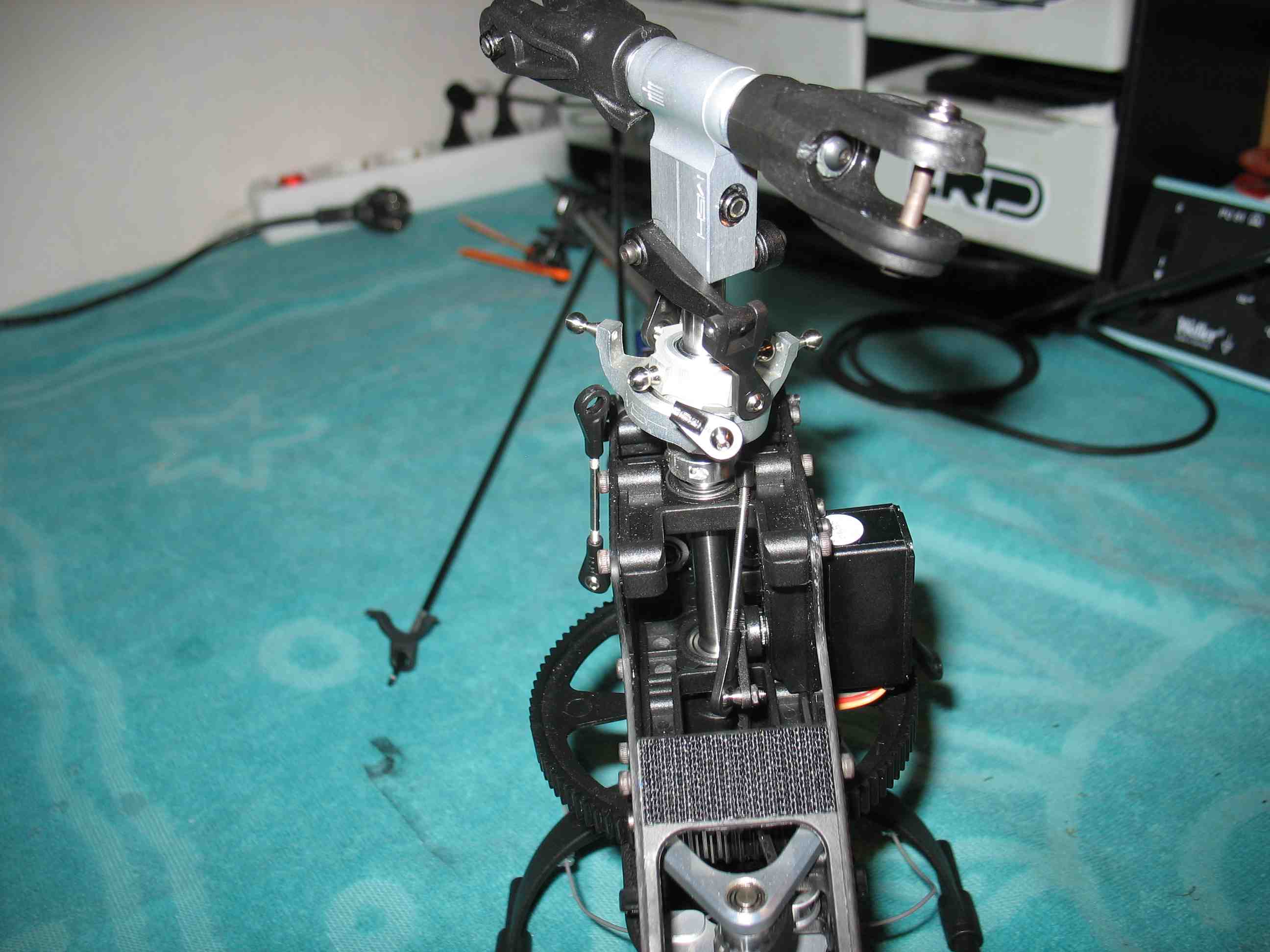 full resolution pic: http://rzavelli.home.xs4all.nl/stuff...s/IMG_2837.JPG I've checked the swash servos by pulling and pushing the swash links, while they were moving up and down over their entire travel range. So far so good. One of the reasons why I chose MKS DS9660A+ swash servos, is their use of metal gears. I will check the splines from the servo horns serrations for damage, or replace the servo horns all together. The right frame plate, properly cracked. Note how the missing arch from the plastic bottom plate has treated the motor, a warning for guiding the ESC signal/BEC/governor cables down the inside of these arches. I luckily had them running on the inside of the left arch, but I'll probably guide them over the top of the motor plate in my new kit. I'll reuse the motor, but hate how it looks like now. 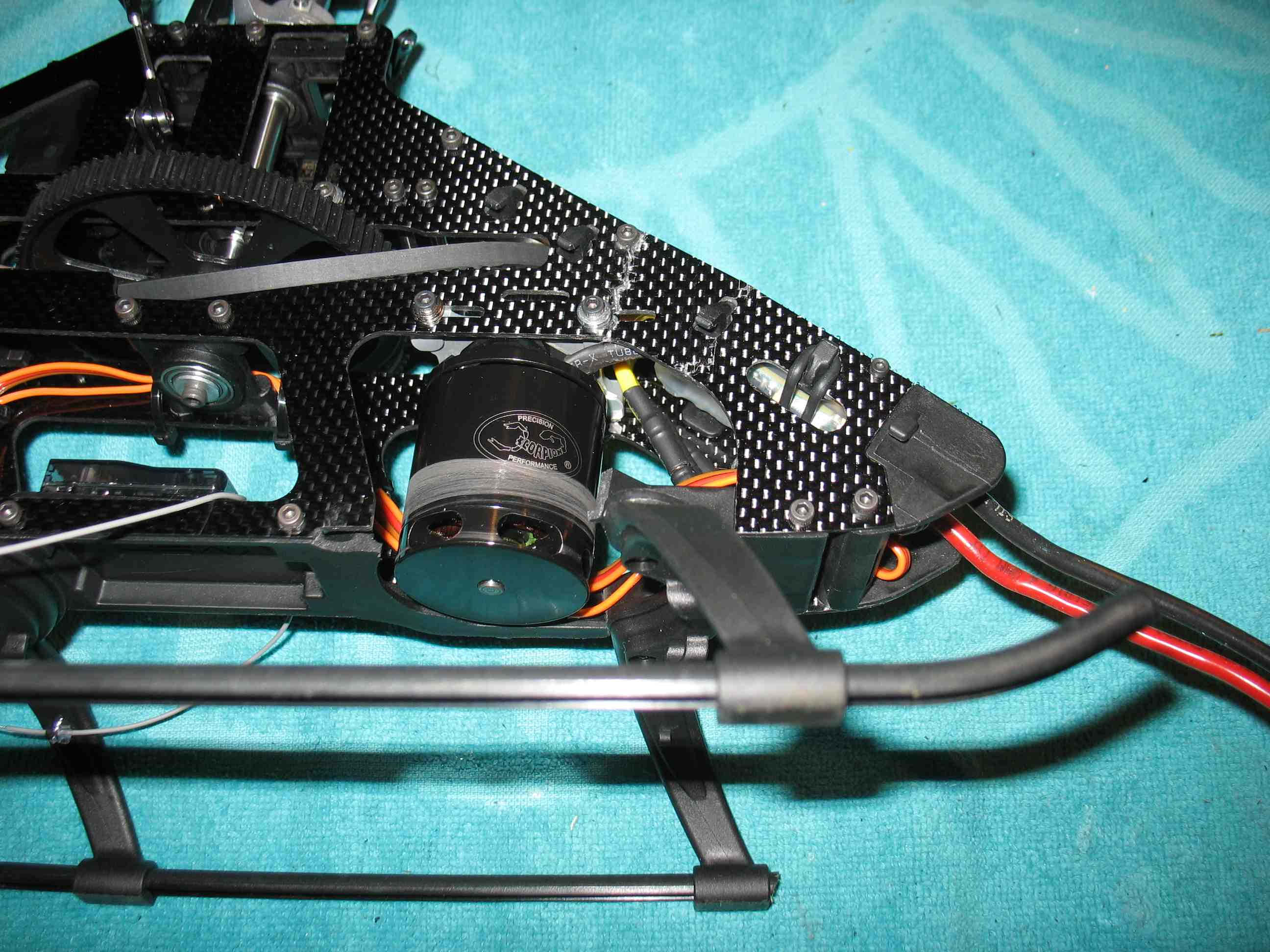 full resolution pic: http://rzavelli.home.xs4all.nl/stuff...s/IMG_2790.JPG Left frame plate, completely cracked too, though less apparent. Skid broken too: 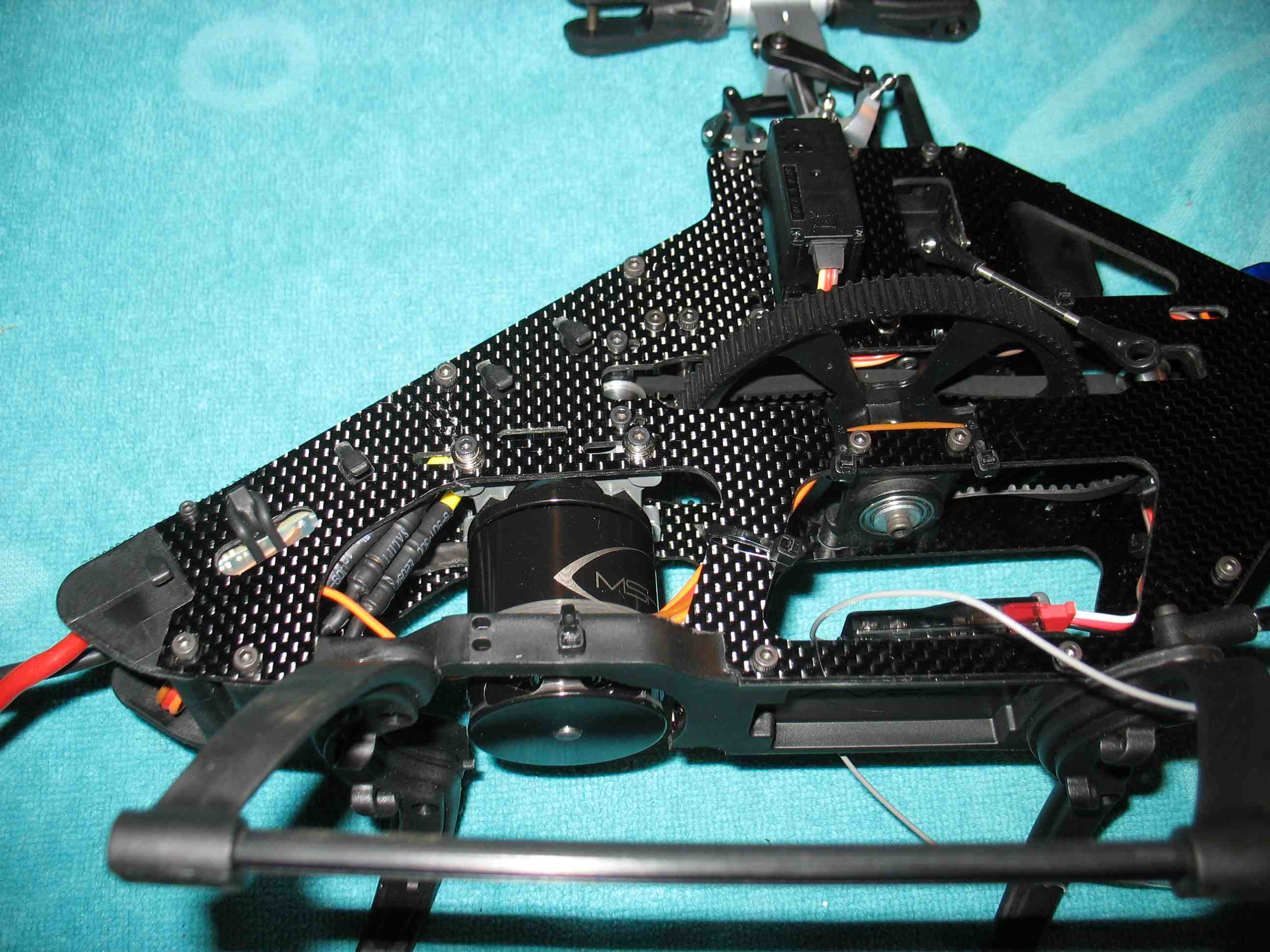 full resolution pic: http://rzavelli.home.xs4all.nl/stuff...s/IMG_2791.JPG Front view: 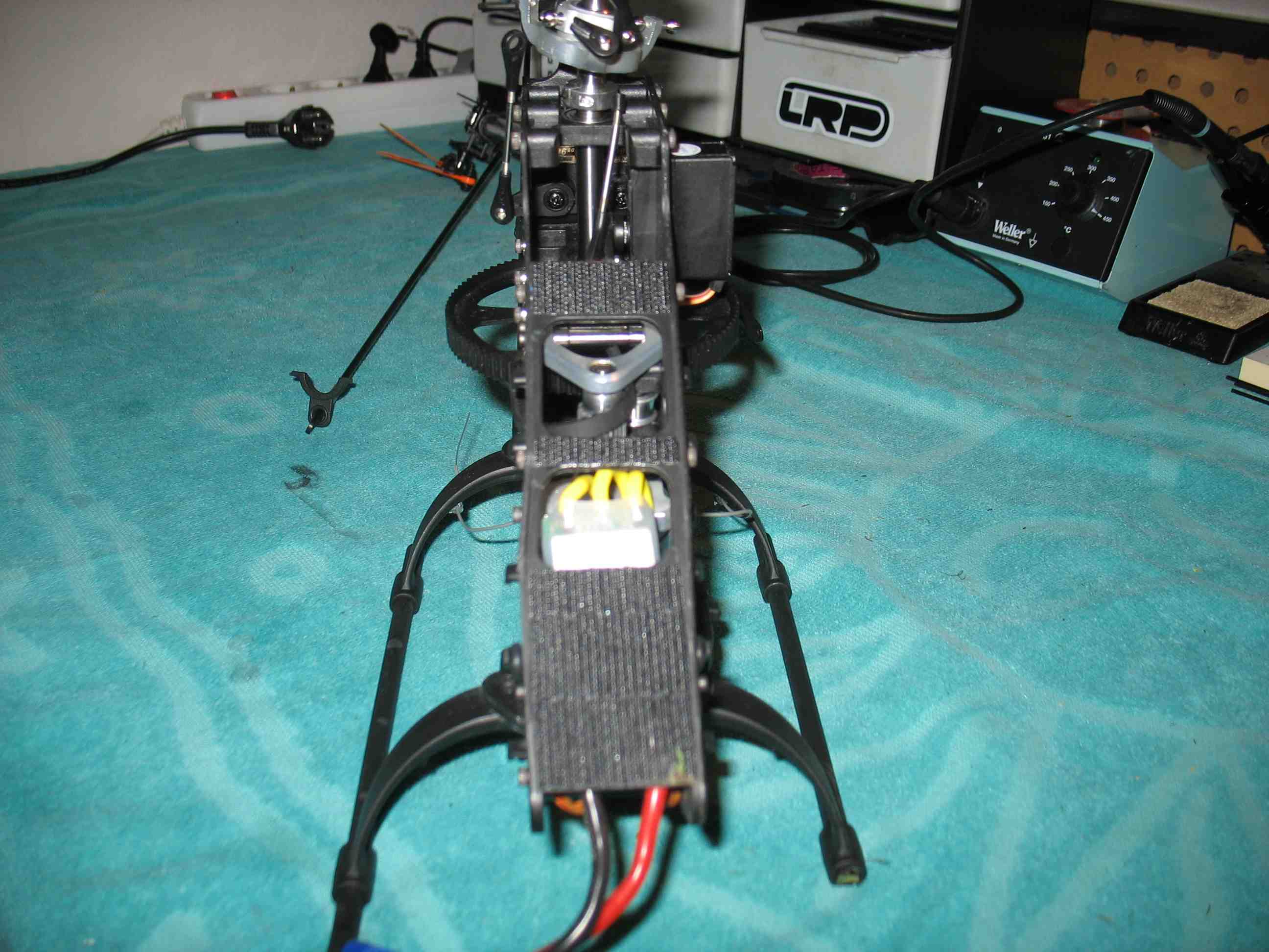 full resolution pic: http://rzavelli.home.xs4all.nl/stuff...s/IMG_2831.JPG The first boom I've broken, on any of my three helis. Small chance the belt is damaged, not sure. Tail boom support is broken too: 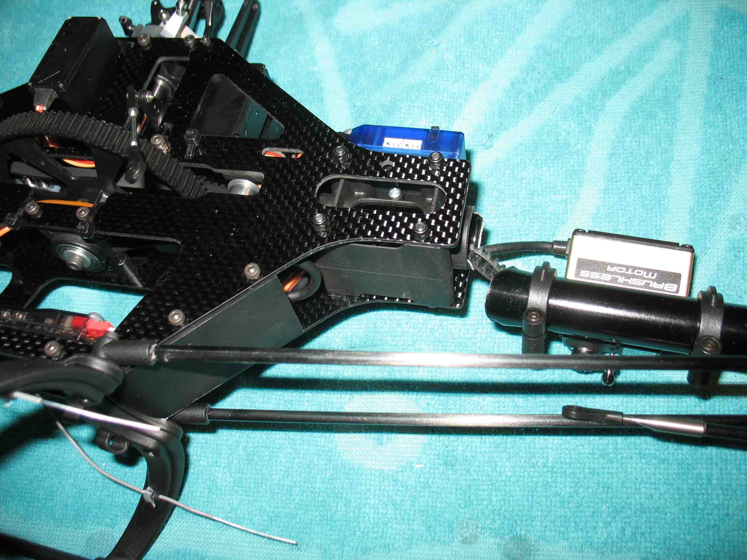 full resolution pic: http://rzavelli.home.xs4all.nl/stuff...s/IMG_2806.JPG Tail boom support holder, I was told these break nearly every crash: 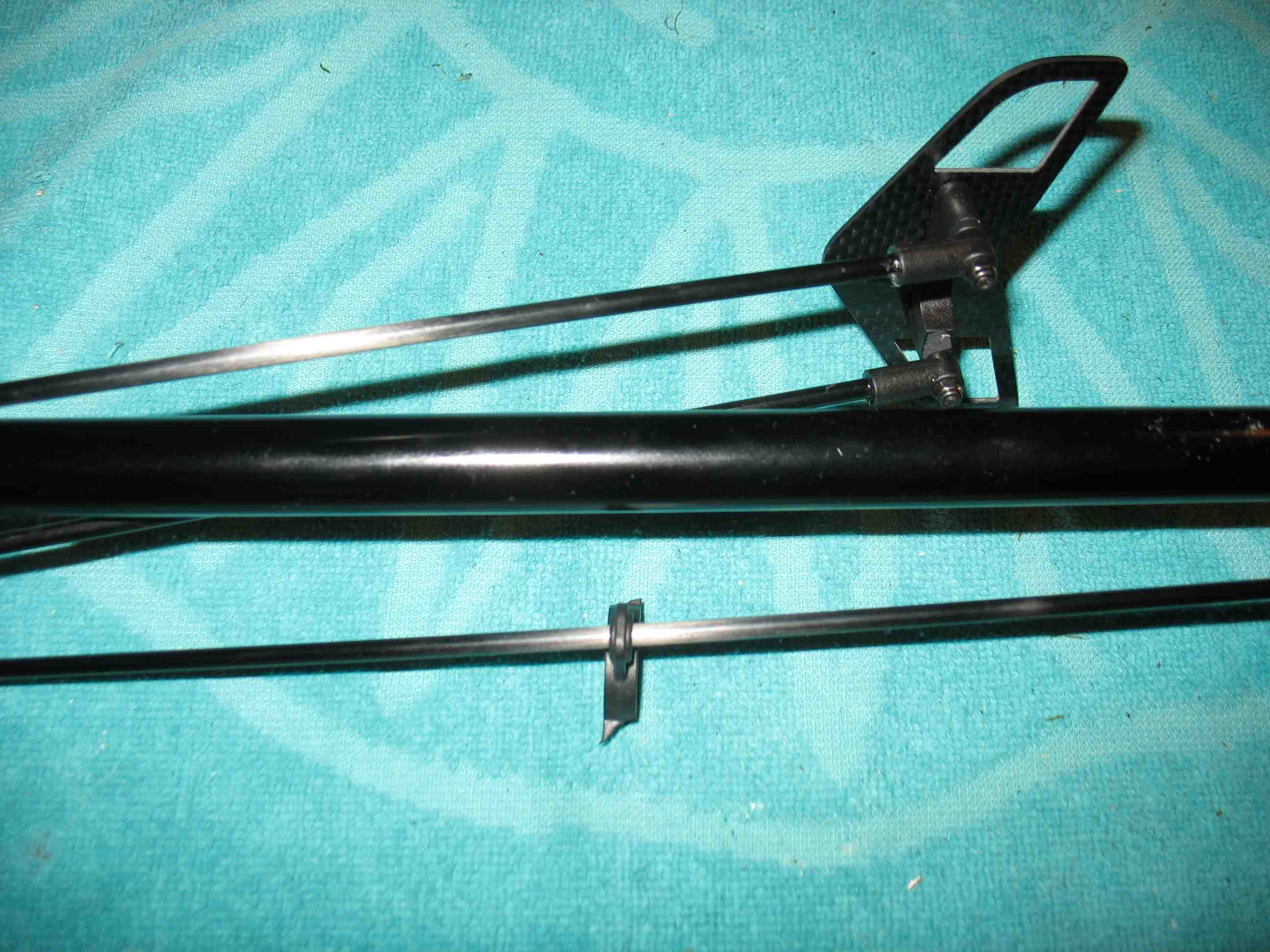 full resolution pic: http://rzavelli.home.xs4all.nl/stuff...s/IMG_2810.JPG The tail shaft assembly still looks good: 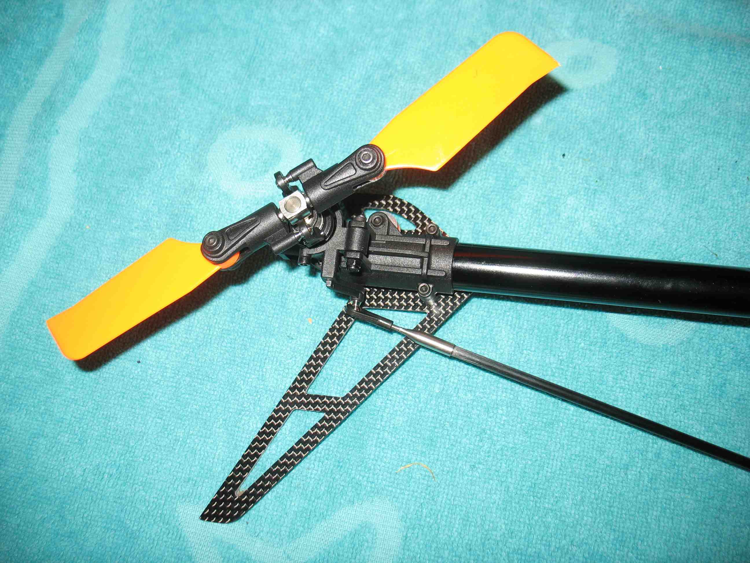 full resolution pic: http://rzavelli.home.xs4all.nl/stuff...s/IMG_2842.JPG Pieces; Pitch links, skid, blade grips, bottom plate arch, canopy post: 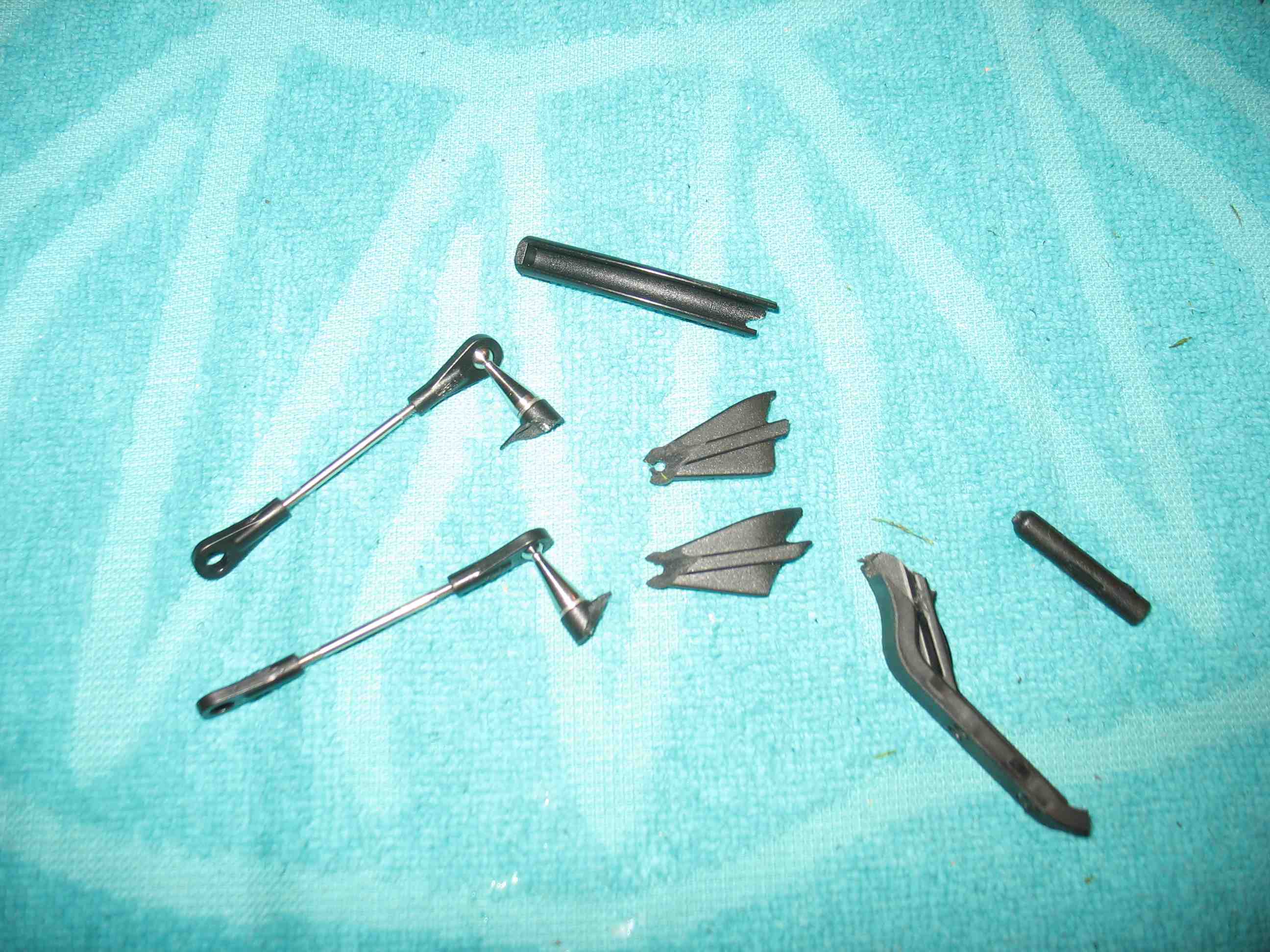 full resolution pic: http://rzavelli.home.xs4all.nl/stuff...s/IMG_2811.JPG Edge 473's: 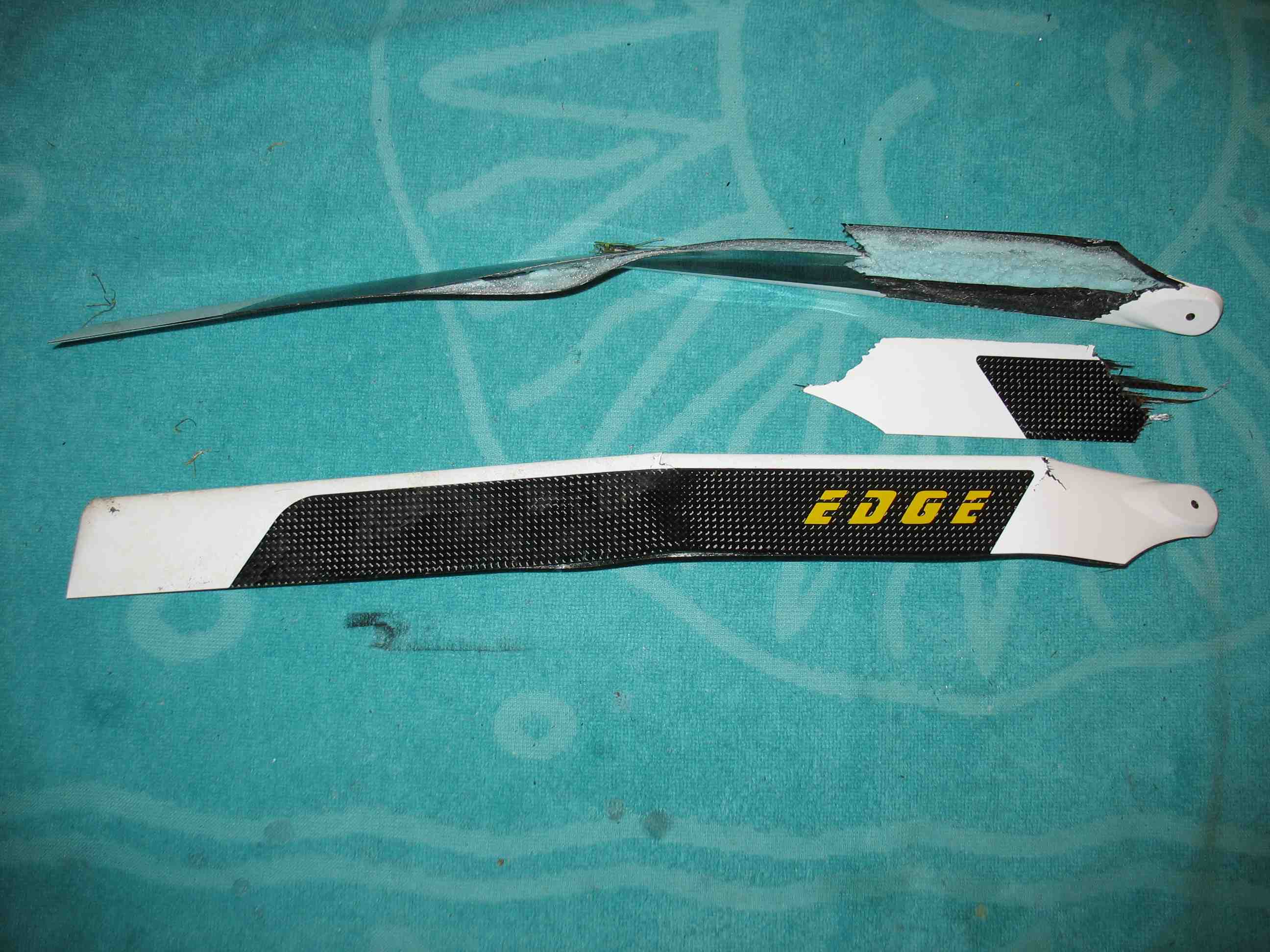 full resolution pic: http://rzavelli.home.xs4all.nl/stuff...s/IMG_2850.JPG The 2700mAh LiPo, which has been sitting in a LiPo bag for the past weeks. There's always the chance of one of the internal metal plates piercing the packaging, so doubt I'll use it much. I'll probably only use it to compare the heli handling to the 3000mAh LiPo I recently bought: 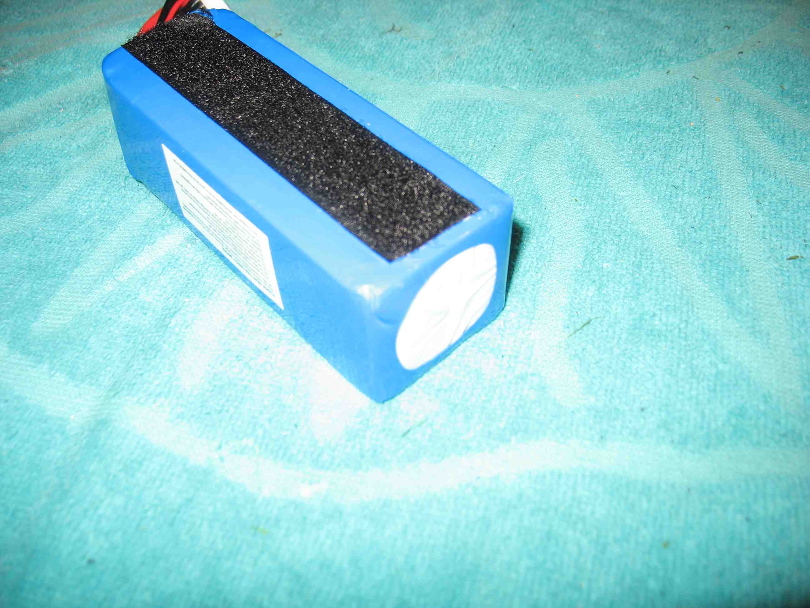 full resolution pic: http://rzavelli.home.xs4all.nl/stuff...s/IMG_2819.JPG 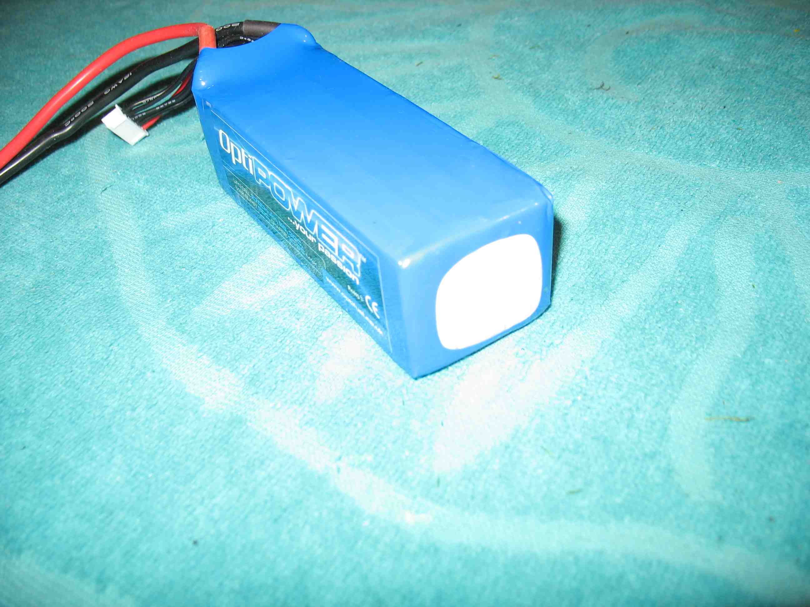 full resolution pic: http://rzavelli.home.xs4all.nl/stuff...s/IMG_2820.JPG Protos build, take two! Wet sanding of CF plates edges. Pictures of this bit again, since I want to include some more detailed info this time. This time I can do all modifications in advance, since I know what will be ahead of me. 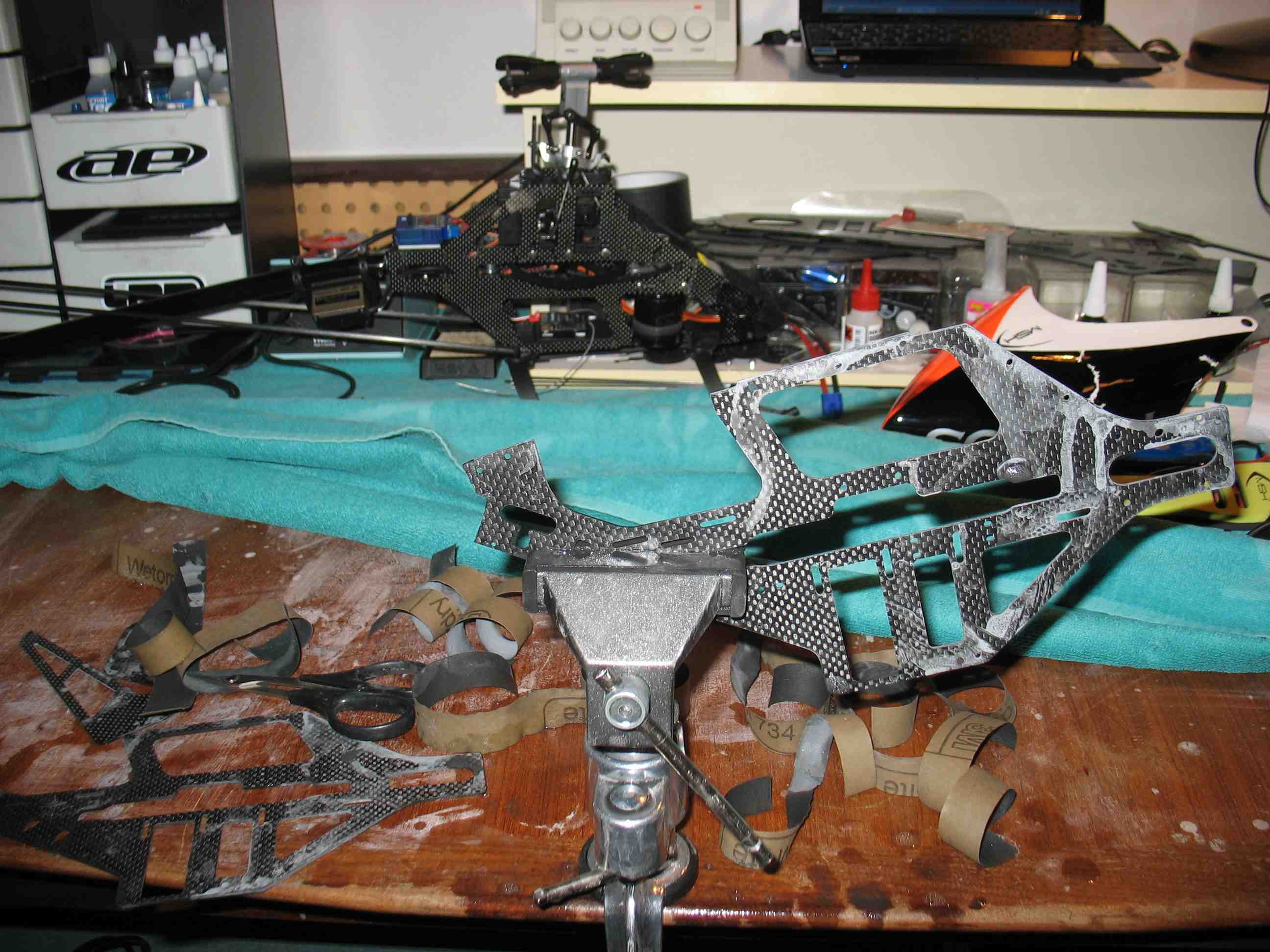 full resolution pic: http://rzavelli.home.xs4all.nl/stuff...s/IMG_2851.JPG The inside of the left frame plate. Some edges I chamfered on the inside, using a wet file. Red: Front swash servo wire slot to run the wire down the inside of the frame, as previously explained in my first build. Slot chamfered on both sides, to prevent wire chafing. Blue: Unused wiring slot. Why did I chamfer the edge then? The FBL unit wires are routed up and down the inside of the frame here, through the tail mount. I just chamfered the edge of the slot, to prevent to wires rubbing against a sharp edge here. Yellow: ESC rubber band mounting hole. Chamfered on the inside, since the motor wires tend to touch the edges here. 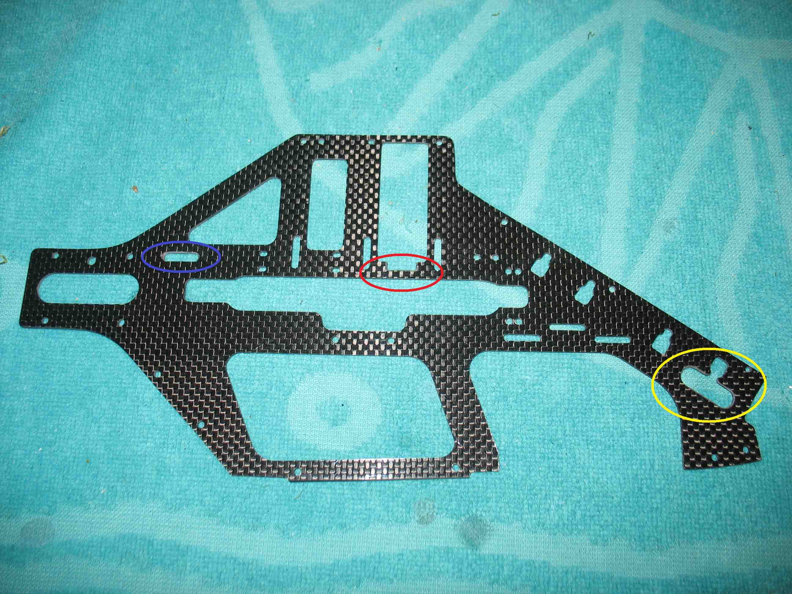 full resolution pic: http://rzavelli.home.xs4all.nl/stuff..._2862_edit.JPG The inside of the right frame plate: Green: Chamfered since I run the tail servo wire down the inside of the frame here. 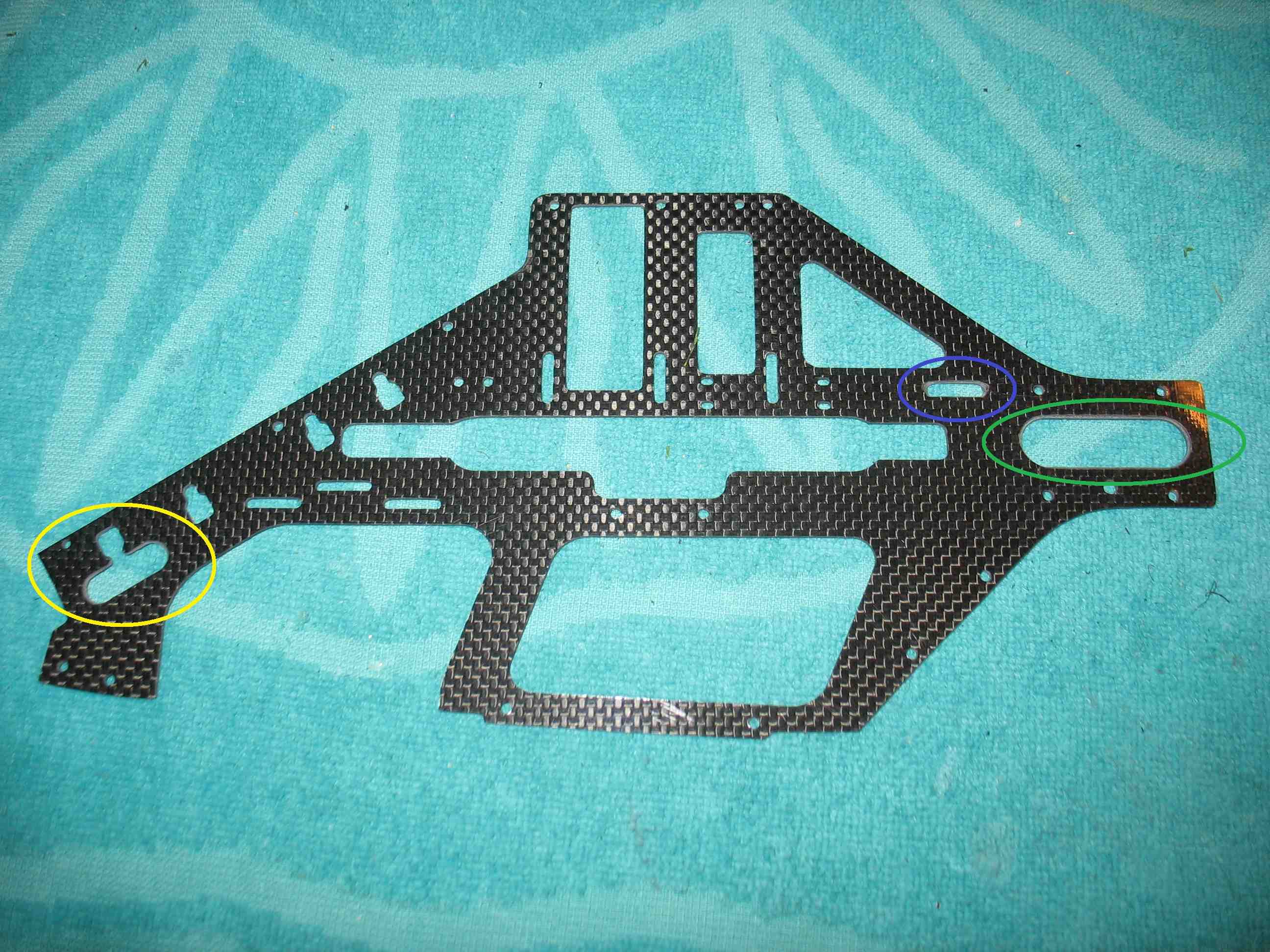 full resolution pic: http://rzavelli.home.xs4all.nl/stuff..._2885_edit.JPG The left frame plate from my first kit was 2mm thick, since it suffered from de-lamination in the middle. The right frame plate was 1.65mm thick. This caused some trouble with over constraining the assembly, as described in the earlier build. I had to file the arches in the plastic bottom plate by quite a bit. Coaxial main shaft bearing alignment needed some serious work too. The left frame plate in this kit is 1.45mm thick, the right one is 1.5mm thick. This translates to this view with an untouched plastic bottom plate. Looks far better than before.  full resolution pic: http://rzavelli.home.xs4all.nl/stuff...s/IMG_2893.JPG Having assembled the swash and head of the rekit earlier, I spent the evening assembling the frame. Only had to file the main shaft 3rd bearing block for about five seconds, to get three perfectly co-axial aligned main shaft bearings. Quite a difference to the previous kit, which required massive work. Leveled the swash at midstick (with gyros de-activated), full negative and full positive. Also adjusted the pitch links to get midstick 0° pitch/blade tracking. Tail tomorrow. Heli should be done before the weekend, whilst taking it slow as usual. Finished the rekit, unfortunately the paint was cracked in three spots, out of the box, but I will be sent a replacement. Used the canopy from the crashed first kit instead for the maiden flights last Saturday. Doinked the rekit on it's fifth flight, doing an inverted auto and being sloppy. Damage isn't too bad, the usual head stuff, blades and tail boom. It's not that I deliberately do it, but I like to push my boundaries, I actually have a rather low overall crash count. I just went through the process of re-uploading re-compressed versions of the pictures, making loading of this build thread significantly faster. So, a long overdue update of my experience with this helicopter. Back in April/May I expected the Protos to handle like a bigger version of the Mini Protos. Wrong. Flies totally different. This thing is relatively a lot lighter than a Mini Protos. I was kind of disappointed, actually. Whenever I do find myself flying this stretched Protos, I usually end up using 425/430mm blades, trying to get decent disc loading to practice technical maneuvers. Slow, with control. Then, it's sort of ok (as far as you can actually use a 500 to practice technical stuff). The only time I like longer 465/470mm blades, is when mindlessly smacking the thing around with zero thought. It moves. However I don't do this often. I've experimented a bit with different types of dampeners and rigid, epoxy glued dampeners as well, no revelations happened. So, the stretched tail only ends up being good to balance the relatively large packs, which fit and balance perfectly btw. Looks weird, a stretch with short blades, but what the hell. A bit of side info worth mentioning, is that I'm 100% confident doing inverted auto's with the Mini Protos (with heavy Edge 353's), even to the point of landing it with a half piroflip. With the Protos, I just don't feel like doing inverted auto's at all. Weird. Here again an overview of the initial setup used in this thread, in case you wondered: MSH51106 Kit Carb - kit ONLY MSH51321 Stretch kit Protos 500 - CARBON ONLY - MSH51115 Flybarless upgrade Kit MSH51335 Low flybarless hub (only stretched protos) MSH51122 Alu pulleys set MSH51135 Tail blades Orange MSH51063 MSH Scorpion HK-3026 880KV YGE 80 with built-in external governor support Mikado 04357 Mini V-Bar "Blueline" 5.3 Express Mikado 06003 VBar Software 5.3 PRO 3x MKS DS9660A+ mini size swash servo Futaba BLS251 brushless standard size tail servo Futaba R6303SB 2.4GHz FASST Micro S.Bus HV Receiver EC3 connectors OptiPower 6S1P 3000mAh 30C LiPo The only changes made so far, are the use of short 425mm main blades and hard MSH 3K tail blades. I might change to the stock boom in the future. I however did end up flying it a fair amount on workdays this summer, cause of the convenience of throwing six packs and a small heli in the car after coming home from work. I will probably do so again next season. My conclusion: For sport flying and smack, perfect helicopter. For any technical/precise maneuver practicing, there are probably better 500's on the market, as far as 500's allow this. However this thing scores on component duration and reliability, bigtime. Plus it looks cool . Small update, I was going through this post and copying it all into a Facebook photo album, started thinking about what I have done with the heli since. LiPo wise, back in early 2013, at first I tried these packs: Optipower 6S1P 2700mAh 30C (400g w/ EC3 connector) Desire Power 6S1P 2600mAh 35C (445g w/ EC3 connector) However, to increase disc loading and improve the center of gravity, I ended up with six of these packs, with the canopy posts moved forward: Optipower 6S1P 3000mAh 30C (498g w/ EC3 connector) One of the changes I made to the heli, is replacing the stock tail boom clamp with the Al. Lynx one, which I had black anodized. Apart from that, I started using the harder/stiffer 3K tail blades. Initially flown with several different brands of 470mm-ish blades, I had a hard time getting used to the ridiculous low disc loading, even at low headspeed. Just too inaccurate to practice anything meaningful. Experimented with different dampeners, no improvement. So I ended up using 425mm-ish sized blades, while still keeping it stretched. Still insanely low disc loading. Never really came to terms with it. It is good for two things: sport flying and hard smack. Tho the latter was fun, it was not what I was looking for in this particular heli at the time. I've flown it a fair bit for the 2013 summer, but haven't really touched it since the autumn of 2013. I'm kind of done with the smaller stuff. It has been collecting dust for over half a year, did six flights today:  full resolution pic: http://rzavelli.home.xs4all.nl/stuff.../WP_001992.jpg
__________________
RAW 420 / RAW 580 / Kraken 580 Nitro / Goblin 700 / 2x RAW 700 / Kraken 700 S VBC-t & Neo Pro / Scorpion motors & ESCs / MKS HBL575 SL & HBL980 / Supra X D4, D6 & S6 / OptiPower / Revolectrix 2x Bump & 5x PL8v2 https://www.youtube.com/kjoer |
|
|
|
|
08-13-2015, 10:27 AM
|
#63 (permalink) |
|
Registered Users
Thread Starter
Join Date: Sep 2011
Location: The Netherlands
|
Reposted everything from winter 2013, bunched together in two replies, with fixed url's.
Small recap from the past years. If i'd actually fly it again, I would only hard anodize both Al. pulleys. I still love the Mini Protos being stretched with 350's, even though I don't fly it anymore. I still absolutely _hate_ the Protos stretched with 475's, so I fly it (stretched still) with 425's instead. The mass to disc ratio is completely off with 475's. Also, the dampeners can't do their job anymore, since they become undersized. Generally, the scaling is off. At Goblin days 2014 in Germany, I asked both Tareq and Dario independently (the latter just being there as a spectator), what they thought of the Protos with 475's, without providing any bias in my question whatsoever. They both didn't like it with 475's either. With 425's, I had fun with it and it did everything ok it was supposed to do, including inverted auto's. Too bad it is collecting dust these days.
__________________
RAW 420 / RAW 580 / Kraken 580 Nitro / Goblin 700 / 2x RAW 700 / Kraken 700 S VBC-t & Neo Pro / Scorpion motors & ESCs / MKS HBL575 SL & HBL980 / Supra X D4, D6 & S6 / OptiPower / Revolectrix 2x Bump & 5x PL8v2 https://www.youtube.com/kjoer |
|
|
|
|
08-14-2015, 11:42 AM
|
#64 (permalink) | |
|
Registered Users
Join Date: Aug 2011
|
Quote:
|
|
|
|
|

|
|
|
«
Previous Thread
|
Next Thread
»
| Thread Tools | |
| Display Modes | |


 Linear Mode

|
|


